This essay is an updated version of a story I wrote about my Mini in about 2001 for a European website dedicated to Mini 650’s. Thus some of the references to races, ideas and people must then be taken in view of this history.

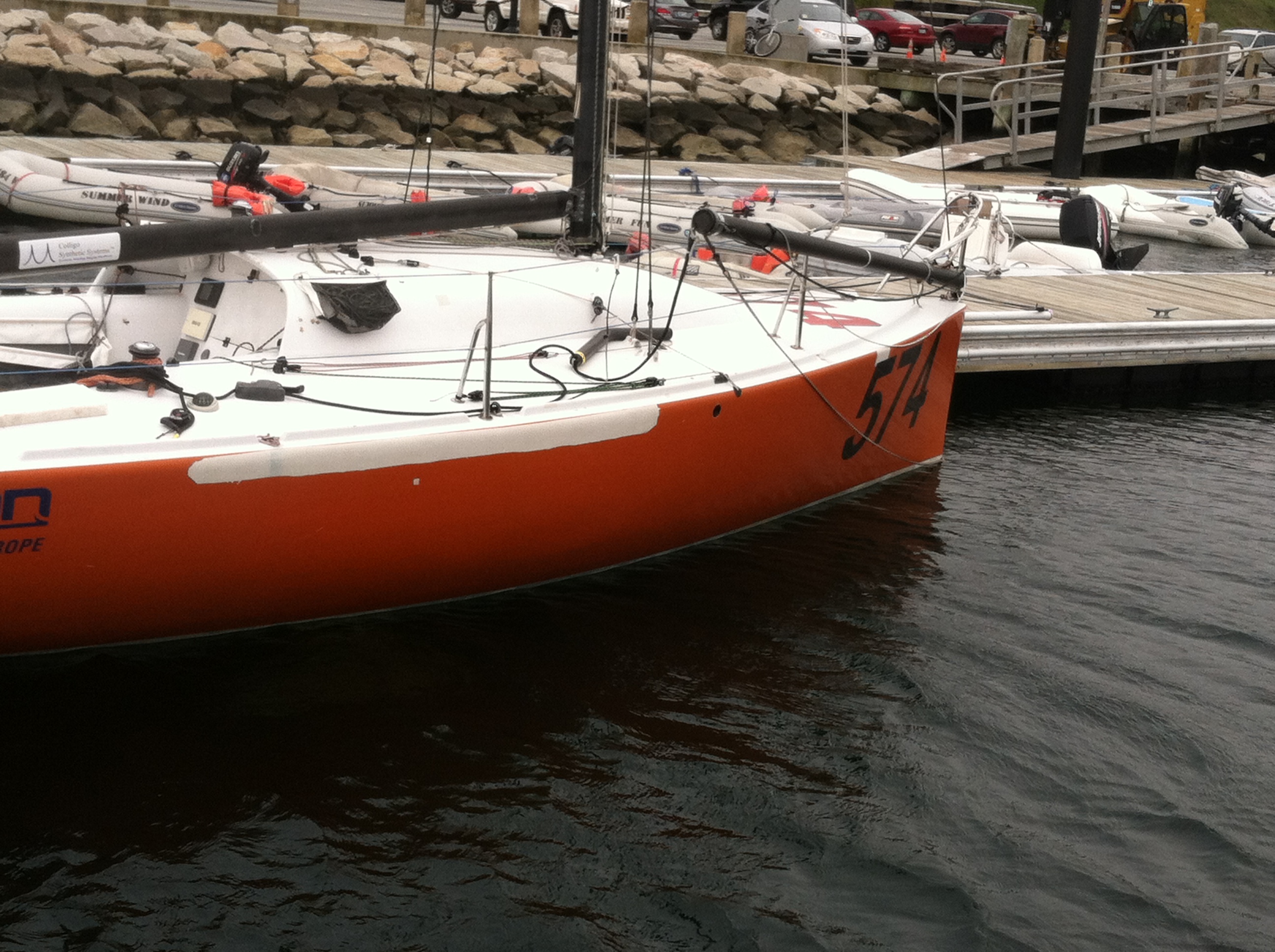
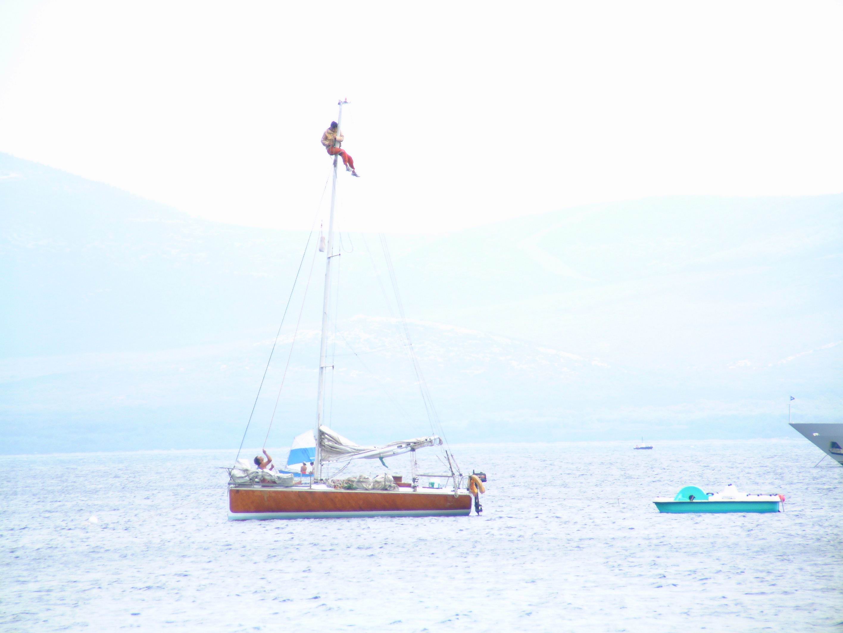
Cooper’s Mini-Alongside the docks at Sail Newport, Summer 2002
NB the images of American Express are courtesy of Marco Romanelli who owned the boat in the early 2000’s and with whom I corresponded for a time. The rest are mine or my long time shipmate and photographer, Don Miller www.donmillerphotography.com

Moving the hull skin from Tom’s shed outside. Me on the left, Tom on the right, Buster the dog’s head on the bottom. Sometime in the summer 1994
I have known about the Mini-Transat, around the edge of my sensibilities, for a long time, but I first became closely aware of the boats in 1991 while working as crew on a yacht in the south of France. There was a copy of “Voile & Voiliers” a sailing magazine, prominent in French sailing circles on board and there was a very thorough coverage of the boats, the class, and the idea behind the race, because in those days it was just one race. Well I was really excited by the idea of it all. A solo ocean race in a small boat that would be cheap and manageable, self-built if necessary, no crew worries, at least not in the crew-gathering department, no big expense for tricky electronics etc. With basically nothing in the way of instruments and not much in the way of rules this was an ocean race I was attracted to. Particularly in this last aspect for a couple of reasons.
I had always been attracted to and followed the solo events and the participants like Chay Blythe, Chichester, Knox -Johnson, Moitessier and then the O.S.T.A.R., BOC etc. I would always be asking myself what I would do if I were in the position the skipper’s in these races would frequently find themselves in. I was attracted to the idea of the Mini-Transat because it offered the opportunity to test one’s seamanship skill in action instead of in the armchair. I thought it would allow me to put into practice all the (great ?) ideas I had accumulated over the years of sailing with a view to seeing just how clever I was.
In April of 1992 I left the job on the yacht and returned to the U.S .to work on my plan.
Design, Concept & Drawings
A good friend in San Francisco suggested I talk to Tom Wylie about designing my 650. I knew of Tom’s reputation because Tom had designed American Express, the boat that won the 1979 race hands down. (It is possible Tom Wylie is the only designer to win this race who is not French, but I may be wrong.)
Tom and I had several long phone conversations (he was in California, I was in New York) where we spoke in rather general terms about simplicity, economy, and such factors as strength vs. weight as a function of cost and time. My brief to him was for a boat that would be strong, simple, easy to sail and good in all conditions. I wanted an all-around boat with no condition where I would say, “Oh **** I am really slow.” The boat has borne out these characteristics in every way. After the second call I sent him some money and in about two weeks I got a hull profile and a deck plan, in reasonable detail but not 100% done. My immediate reaction was that he had done very well putting down on paper what I had in my head. I thought that we were very much on the same wavelength. We had another couple of talks adjusting a couple of small things, back came a revised drawing and that became the boat I built.
As can perhaps be seen from the pictures, this boat is quite different from the “standard” French design. Remember it was designed in 19923 before all the new hull Box Rules were implemented. In fact it was Grandfathered in Jan 1995. It is distinctive in narrow beam and low freeboard.
The boat reflects ideas that Tom and I agreed on early in the planning, as explained below.

Heading east across the Rockies on I-80 about Thanksgiving 1994
Point 1: A basic boat should not have a high beam to length ratio. (current minis are 6.5m long and 3m wide) This is because when a beamy boat heels over the water plan-form becomes extremely asymmetrical and out of balance. This is one characteristic that requires the wide boats to have two rudders, and now I see some boats with perhaps 3-4 other blades in the water. I think all these blades are really to compensate for the asymmetrical shape created when the boat heels over. Some of the boats I see now have foils moving fore and aft and I have seen sketches of fins that move side to side in the boat.Well, all that is great if you can either design and build it yourself or have the money to pay someone to do it. In any event all of this small delicate detail requires design time, engineering time, construction time and weight and must be paid for and THEN you must learn how to sail the boat so rigged.
For the same LOA, a wide boat has greater wetted surface than a narrow one. For the same displacement and length the canoe body of a wide boat must be (shallower) flatter. This wider flatter shape combined with additional surface area means the boat will have more drag in very light air and pound upwind and in waves in any breeze.
In a wider boat, for the same level of construction technology, in other words the same finished weight per square foot of hull, there is more sq. footage of hull so it must weigh more for a fixed LOA. If it weighs more, then you cannot have such a heavy keel if you’re going to keep the total displacement down, and bear in mind about 25%-30% of the designed disp. of the mini-boat is in the crew weight and consumables. In my case, my weight alone accounts for 10% of the displacement of the boat (I was at the time 6’4″, 210 pounds) in ocean-going trim. It is even higher in day-sailing trim, more like 13%. So you either have a less powerful boat OR you need to have a lighter structure. So for a wide hull on a fixed LOA a lighter means more expensive materials and more sophisticated people building it. I understand Amco, a prominent French yard outside LaTrinite is now doing carbon pre-preg hulls for say USD 60k just for the hull and deck, maybe. And don’t forget all the blades are additional wetted surface too. Say three blades in the water with each blade averaging 4.5 feet (deep) times 1.25 feet in average cord is 6.75 sq.ft. times three foils is 20 sq.ft. This is about 20% of the wetted surface of my boat. Not only do you have the weight of the blades but there is the weight of the structure through which the blades operate in the water and of course the cost to design and build.
A boat with less wetted surface and a narrow beam waterline, and roughly the same sail area will need less wind to break out and surf. For instance, I have sailed at 10 plus knots of boat speed in 9-11 true wind speed, at 90 degrees apparent wind angle with a 600 sq. foot kite, with the equivalent of half a tank of ballast. In very light air I can sit forward like on a Laser, get the transom out of the water (where it is fully immersed in the pictures of all the French boats I have seen) and reduce the wetted surface even more.

My brother in Law and his wife and kids live just north of Salt Lake City, so we stopped there for a visit, feed and bath.
Point #2: Wide boats generally are fitted with two rudders, which in my experience are a drag, literally. On a small boat the lower portion of the weather rudder is dragging in the water. On an open 60 the weather rudder is fully out of the water, because the transom is so wide relative to the depth of the rudder, although Desjoyeaux had kick up rudders like a Laser. While this is a good idea it still requires design and engineering time, weight and money to implement. When I sailed a twin-rudder Quest 30 from Newport to Plymouth, England, the steering was very heavy. Most of the twin rudder versions of this boat have been converted to single rudders.
Twin rudders are also exposed to banging into things in the ocean and they
are heavier in total than one. I have measured one of a pair of rudders on a French boat and it is the same surface area as mine, about 3.25 sq.ft. So now with 2 rudders, the total surface area is 2 times the surface of one rudder PLUS they require more mechanism to operate, which is additional weight and another thing to design, engineer, pay for and break. As to net performance, in the 1991 race (I think) the first boat was the widest, skipper’ed by Desjoyeaux ( with the first canting keel on a mini, or any where else for a long time-probably since Red Herring but that is another post…)and the second boat was the narrowest, at about 6 feet, under the command of Patrice Carpentier. Two very experienced sailors, even then, finished within hours of each other.
As far as I can tell after looking at this scene for 17 years the only true
advantage to a wide boat is in two-sail power reaching. David Adams won the
BOC 50 class in a relatively narrow, simple, strong, single rudder boat, and
he sailed the daylights out of it. Steve Peggengill was what, 2nd (?) in a
generation-old boat with similar characteristics and an economy program (compared to the French) in the 60 foot class in the next race I recall.
On the subject of design, engineering and construction costs, I mention that the boat was originally drawn with a canting keel. I was OK with the idea but eventually settled on a fixed keel and water ballast in order to minimize the three elements noted.
These are some of the factors that became the rationale for my boat’s design. Easy and simple-to-build became important as I progressed into the building of the boat.
Construction Phase
Initially I had hoped to have enough money to hire a boat-builder and I even went as far as getting a quote from Eric Goetz, in Bristol, Rhode Island. Unfortunately I did not have the money so I had to resort to building it largely myself.
The construction of my boat was great fun and a great lesson in boat building. It happened in about 5 stages. Initially Tom Wylie suggested to me that the only way to get people to pay attention, and potentially sponsor my program, was to have a boat, or at least a photo of a boat so I could be taken a little more seriously. He proposed a course of action that I followed.
Remember that Tom Wylie is not “just” a designer but has been ( and remains active today) a boat-builder since the early 1970s. There are several boats in the 30-45 foot size in different parts of the U.S. built by his company. His 1978 650 design American Express was built by him in cold-molded wood and it was job #25 or something like this, in his shop in 1978.

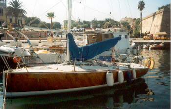
The “other” Wylie Mini, American Express taken in Brest in 1993 as she prepared for another atlantic crossing. 15 years old and still going
As of the mid 2000’s American Express was still going and had finished a race in the 1990’s sometime.
Here is how we built my boat or at least the hull.
He and two of his crew set up mold frames on the strong back. They then laid ribbands over the stations and screwed these down. So now the shape of a boat was visible. This took three guys about 2 days. Then they took H-80 Foam and bent it over the skeleton, putting shaping slits in the sheets as required and holding these foam sheets down to the ribbands with screws. By the third day the foam was on. Then they took uni-directional Carbon and S glass and laid it over the foam according to a laminate schedule Tom had calculated. Using vinylester resin the boat was laminated on the outside skin within a week. It was the slickest thing ever. It was a long way from a boat but you couldn’t tell looking at the photos, which was the idea. He did another clever thing.
He took a can of white, house paint, and painted the bottom, the water plane of the boat, and also painted on a red boot stripe. The topsides he left black from the carbon. The result as you will see is a pretty cool looking boat except there was not much to it. But now I had a “boat” to use for raising money. I took some pictures, seen above, of the whole caper and used them in my presentations
When I had the next pile of money we made a cradle for the boat to sit on. Then we laminated the inside skin and put on a transom. This was again about a week’s worth of work. By this time I had decided I was going to have to get the boat to the East coast, from San Francisco. This was also a great adventure.
First I bought a trailer of suitable proportions. We then tabbed some cheap construction plywood “bulkheads” onto the inside skin of the boat. Remember there was no internal structure at this point and I wanted to keep the boat from flexing around too much while being towed 3000 miles. We then bolted some framing 4×2 timber to the bulkheads and bolted the boat, upside down to the trailer fore and aft. We loaded all the rest of the materials into boxes, lashed them to the trailer, hooked the whole lot up to another friend’s Volvo station wagon (with 500,000km on it) and drove across the U.S. to New York.
Through another friend who owned a boatyard I was able to put the boat in a shed he was not using and I started to put the framing inside it.

At this point the skin weighed only about 200 lbs or so. Easily maneuvered by a couple of healthy lads.
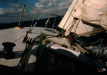
There are basically two longitudinal members running fore and aft in the boat. In the middle section of the boat around the keel area, they are the vertical face of the water ballast tanks and under the cockpit floor they are faces of a void into which the flotation foam was poured. Because both of these faces are fastened from the deck down to the floor the whole boat is really super stiff. I can wind the backstays on super tight and the lifelines do not move an inch. Then I worked on building the deck.
Again more friends came to the rescue, this time in the form of Don Watson (now the Boat Builder at NEB in Portsmouth, RI) who was at the time head boat-builder at Concordia Custom Yachts.
How We Built the Deck and Cockpit
Because the deck was really quite flat (like American Express or a J-24) and without a cabin it was very easy.

American Express on the wind-With a flat deck that actually came out of the mold for a Moore 24 and which Tom trimmed to fit the hull… It does not have to be complicated

S.A.I.L for Kids at sea en-route to France Sept 1995.
Flat deck just like her Mummy…
A “cabin” was not required by the rules at that time. On a flat laminating table we laid out the plan shape of the deck from the plans. We cut H-80 Divinycell foam to the shape and placed it on the table including heavier foam in hi-load areas. We then applied the laminate using epoxy and vacuum-bagged the whole lot down to the table and left it to cure overnight. In another corner of the room, we built a mold of the actual deck shape with the camber it does have. The next day when the first layer had cured we took the foam, with laminate on one side and placed it, laminate down, on the mold. We held it in place with screws again and then applied the “other” skin to the foam and vacuumed it down. While that was curing we made another panel which was totally flat shaped to the rough outline of the cockpit floor and vacuumed that down. The net result was after 5 days, with 3 guys, I had one deck and one cockpit floor.
We tied the deck and cockpit to the boat, now on its trailer, right way up and drove back down to my little shed in the boatyard in Connecticut and went to work building the internal structure. This was the easiest but the slowest. The main reason was it was the first time I had gone solo in building the boat. I had just undergone a crash course under the tutelage of some of the best composite and boat -building guys in the business and I had learned a lot but now I had to go it alone, so I went extra careful.
Back in my shed I had stored a sheet of 8mm marine plywood. I made cardboard templates of the parts I needed to put in place. These included the two longitudinals, plus a third one under the centerline of the cockpit floor and a watertight bulkhead across the forward end of the cockpit between the bottom of the cockpit and the hull. (Refer to the pictures)

The water tight compartments with the flotation foam installed. All this structure made the longitudinal axis really stiff. The transverse bulk head forward makes the rudder area water tight in the event of a serious crash with the rudder. My all suffering wife Jill, under the hair made it all possible.
The end result is that I had under the cockpit two spaces which are filled with foam and another two spaces which became sealed off and watertight. One advantage of this was that in the event something hit the rudder and damaged the transom the boat had a watertight bulkhead about 2 meters forward of the rudder. It also made the boat very stiff fore and aft. After I had made sure the boat was level and upright, I cut out the plywood shapes and held them in with clamps and battens. I put in the fillets and then tabbed the plywood in with 4″ fiberglass tape and epoxy.
Why plywood instead of foam panels? In the size of the parts we were using the weight saving is very small if any, the plywood material is cheaper and I did not have to spend time making flat panels. Plus I could go to the local shop and buy another sheet when I needed it.
This all sounds pretty easy and fast but considering I was reading the book on boat building and fiberglass work with one hand and spreading epoxy with the other hand it took a while. Also I was fundraising, calling suppliers, and generally doing about 100 things as well as actually building the boat.
At the time this was all going on I was living in New York City and the boatyard was in Mystic, Connecticut, about 130 miles to the east at the end of Long Is. Sound. Typically I would work for 4 days in the middle of the week, staying on the sofa of my favorite friends and then go home for the weekend. In the midst of all this, through my fund raising endeavors I was introduced to Richard Pierce who operated a branch of the Offshore Sailing School in Jersey City opposite NYC. One thing led to another and he offered me the use of the warehouse in which the school stored their fleet of instructional Solings in the off season. This was good because I could “commute” home at night and still be working on the boat during the day. This worked well for a while.

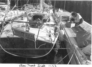
In the Offshore Sailing School shed in Jersey City. Deck tank faces & baffles installed. The chart on the wall is the Atlantic chart of the course. Jill still smiling.
As it turned out I ended up with another offer for boat-building space, from again another mate in the business, but as usual up in Bristol RI.
Barrett Holby of Holby Marine has been a boat-builder in Bristol for the last 20 years or so and is currently the builder of the Quest 30 and 33. So back up to Bristol we go. It was a bit easier being back in the company of composite boat-builders who took pity on me and would say things like, “No not that way, this way…” as I was about to do something really dumb.

At Holby Marine in Bristol RI. The tank baffles are glassed in. One of Barrett’s very successful Rodger Martin designed Quest 30’s in the background.
During this stopover I put in the main bulkhead at the front of the cockpit, the water tank faces including the baffles, more float foam, the watertight bulkhead in the bow, the deck and the cockpit. Climbing around inside the boat tabbing the inside of the deck joint was pretty grueling work and I take my hat off to the guys who do it every day for a living. It was very weird too because, being all carbon it was almost literally pitch black. Even the light from quite strong lamps would be absorbed by the blackness of the carbon. A very eerie feeling.
So now I had a hull, deck, interior structure but no method for attaching the keel. The other detail missing was a deck/seat in the cockpit. This ended up being 8mm marine plywood on supports. The overall effect is like the deck/cockpit arrangement in the America’s Cup boats, where the cockpit floor extends all the way across the hull from inside skin to inside skin and the “deck” is just basically something to sit on. You can see this in the pictures.
Next stop was to fair the hull and prepare it for paint. Off to another mate’s shop, again around the corner in Bristol.

At Brian Bennett’s shop down the street from Holby in Bristol RI. While I was there Brian was fairing the mold for what became the Viper 640
Brian Bennett ran a shop that did bottom fairing and paint jobs for the local Etchell’s 22, and other one-design fleets. It was here I built the cockpit/deck structure and did the filling, fairing and painting.
So in I go and start sanding and filling and more sanding. That was even harder than tabbing in the deck. I worked 10 hours a day on the long board, by myself sanding and filling and fairing. It was hard work and discouraging just grinding away all alone but I figured since I was going to be alone for 2-3 weeks in the race it was good mental practice. After about three weeks of this I called it done enough and turned it over to Brian who put some undercoating on it onto which I could apply basically any paint I wanted later on. He also gave me an old J-24 rudder he had in a corner. Cross another 2 things off the list.

Out for an afternoon sail. Perhaps the only time a Mini has towed a Dinghy? My wife, Jill, and son Ned, steering.
The Keel
By this time it was looking more and more like a boat, and the next thing it needed was a keel. The next stop was to Eric Goetz Custom boats back up the street a few hundred yards. Bristol by the way is a small village, maybe smaller than La Trinite. In one section of town there is an old stone building that contains a boat-building supply company, marine plywood shop, and Brian Bennett’s shop. A big hardware store is around the corner. Most of the boat-building happens on a small street called Broad Common Rd. Along this street is Goetz Custom Boats, Resolute Shells-(A Carbon rowing shells builder that Eric started) Carroll Marine, Holby, GMT (carbon spars), Hall Spars and Rigging, a couple of other boat-builders who do cruising boats, and a really fantastic metalwork shop called CAM Engineering. It is like living in a candy store for someone interested in the finest boat-building and outfitting in the world.
So back to Eric’s. I arrived on the appointed morning as he was pulling the last boat he had completed out of the door. Eric has a very interesting business policy. Once every week at the morning break the people in the front office tell the guys on the floor what is going on up front and the production guys discuss what has been happening on the floor, in front of everyone. There is very good communication between all the staff and I think this contributes to the excellence of his boats and the efficiency he brings to boat-building.
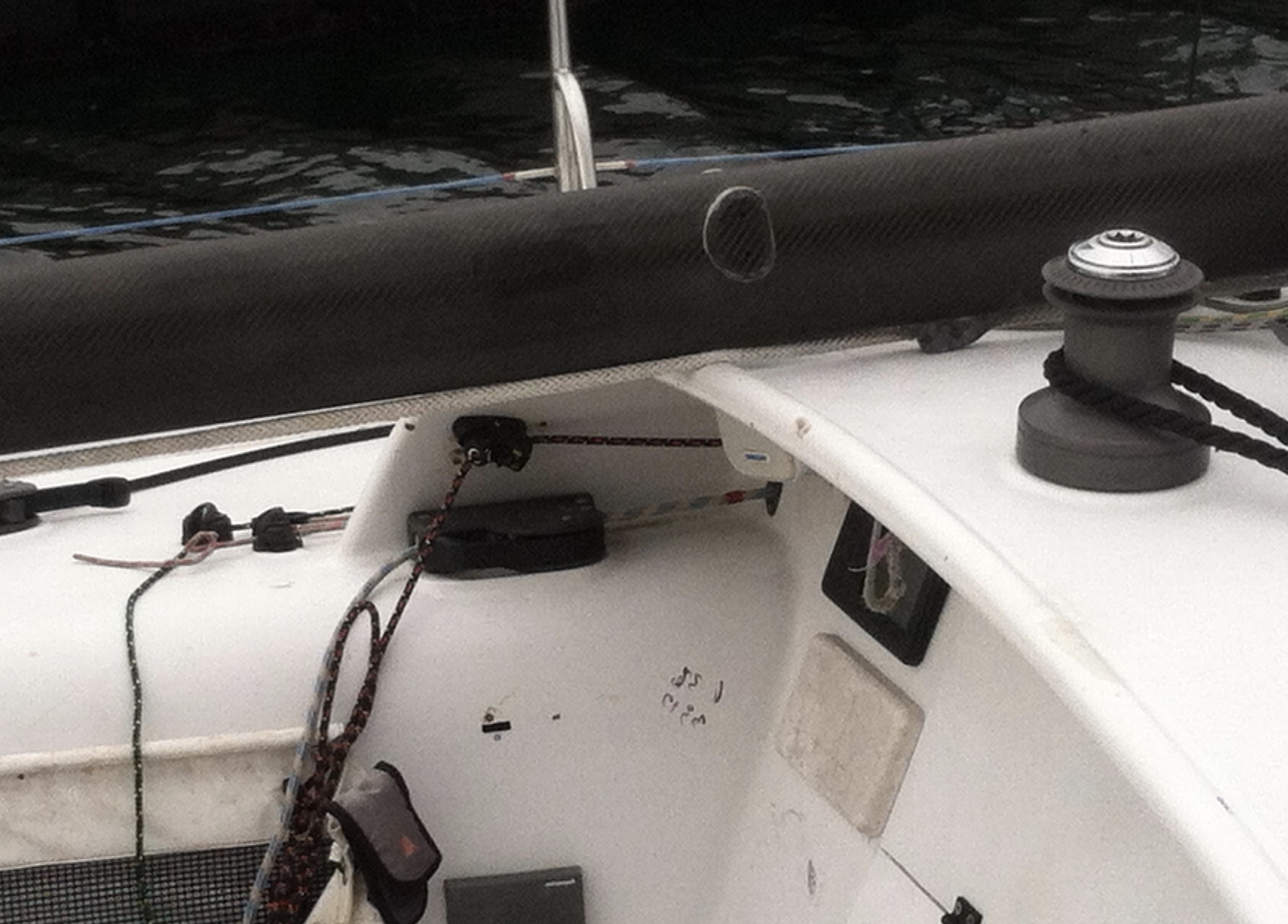
So I was introduced and the outline of what I was attempting was described and the extent of the work to be done. After the break we rolled my boat in, set it up in a corner and I was introduced to “my” two workers, Judd and Bilzo. I had about a week between other Goetz projects to get the keel installed and a few other little things done. We discussed the needs and the plan. For this work there was no detail from Tom, which we had agreed on in the first place. Therefore the engineering and the laminate schedule for the keel box was done by Eric’s team. Again as you can see from the pictures, below, it is a fairly “normal” box into which the top of the keel fits. It was subsequently held in place by two transverse bolts made by CAM Engineering seen in the pictures of the interior, below.

Testing the stability Summer 2002. I could not get her to 90 degrees with a 4:1 tackle.
While all this was going on I needed to get the actual keel.
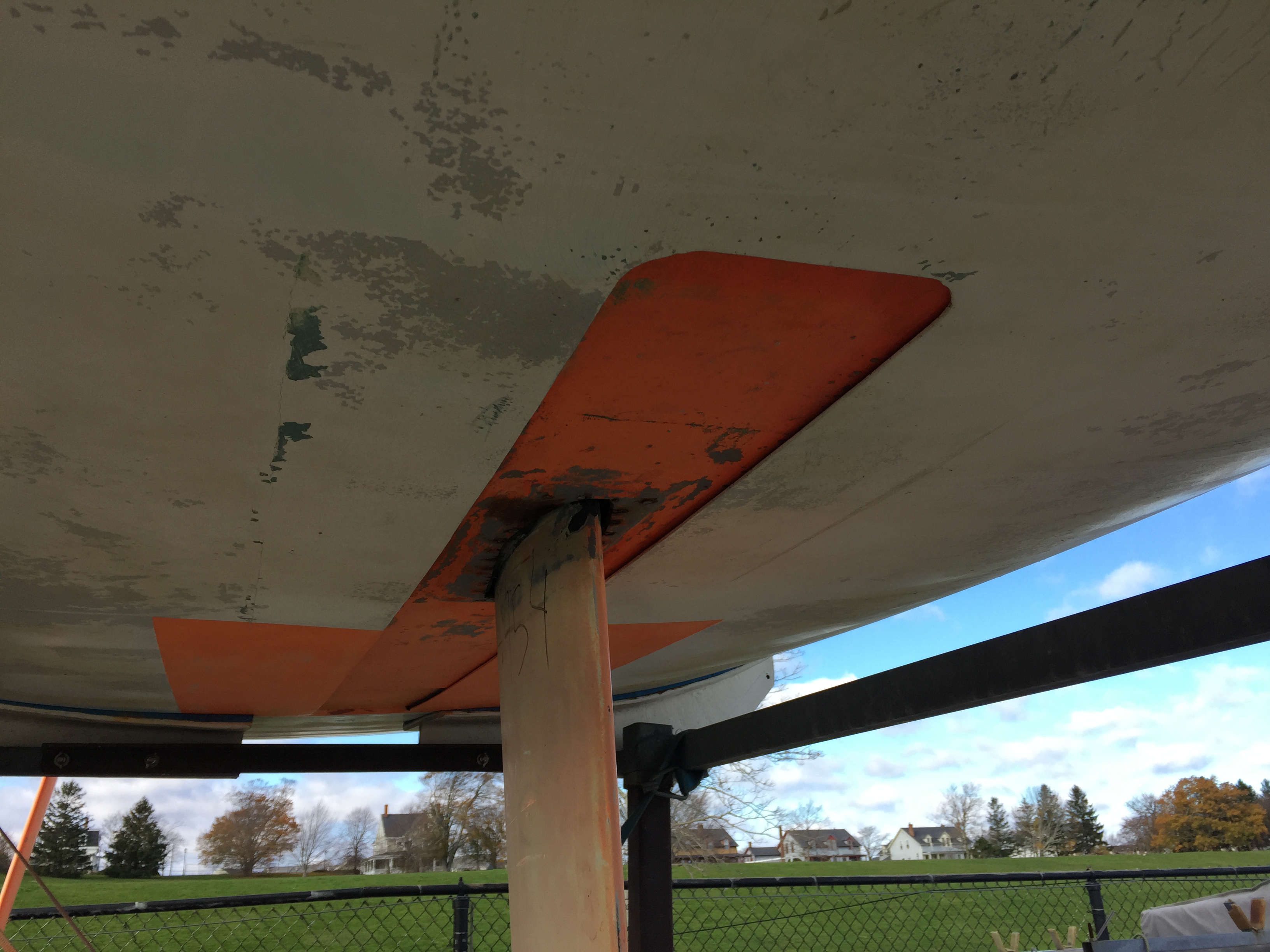
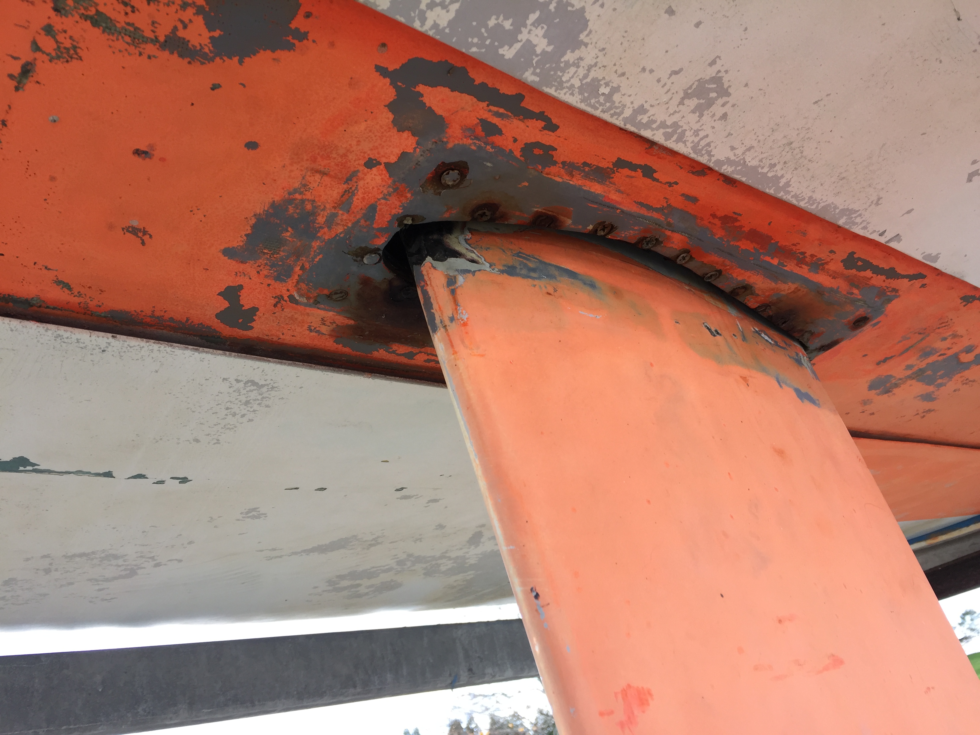
The keel, the fin and the bulb, is literally from a Melges 24. The whole keel assembly comprises a carbon strut built by Omohundro, in Nevada, for Melges, with a 750lb. bulb, the diameter of which meets the bulb diameter rule. When the Melges 24 was being developed it was designed to have an aluminum mast so it had a heavier and stiffer keel. When the boat finally came out with a Carbon mast they changed the keel to make it lighter. Well, I have a prototype earlier model keel, which is heavier. The good news is it was not much money and it would do the job almost perfectly. The bad news was it was in Wisconsin, about 1,000 miles from Bristol. After being unable to find a way to get it from there to me, I decided I’d better go get it. So, I drove to Wisconsin, picked up a U-Haul trailer, put the keel on the trailer, paid for the keel and drove back. And yes they really do have cows in the front yard at Melges Boat Works. That was about 4 days door to door, sleeping in the car and dining while driving.
When I got back to Goetz they were ready to put the keel in the box. We turned the boat upside down and laid her on soft padding and lined it up under a small crane. Hanging on the crane was the keel, upside down. We lowered the fin into the slot and checked the fit. At this point we also installed a screw thread in the top of the fin that would permit the fin to be screwed up to the top of the box, which was tapered, so it would be a super tight fit.

The Melges 24 keel going into the boat. Eric supervising
When we were happy with the fit we pulled it out again. We then coated the top of the fin with wax release agent (so I can get it out if I have to), put into the slot lots of epoxy with thickening agent and dropped the fin into the hole again for the last time. We then trued it up with two lasers and secured it so it would not move while the epoxy was curing. After the epoxy finally cured we bored the holes for the transverse bolts and installed them. Now I had a fin. We turned her over, right way up and put it on stands back in another corner. Now she was really looking like a boat. The last jobs were painting the deck, water proofing the inside of the ballast tanks, installation of the mast collar and mast step, floatation foam in the bow and some tabbing in an area I was too big to get to, done by one of the smaller guys.
While all this was going on I found a bow rail in a secondhand/consignment store in Newport that I bought for $20. CAM Engineering modified this rail to fit the boat and it worked as If I had had a custom design done for the rail. Down the street at Carroll Marine, I was invited to a tour of their parts room to relieve them of anything I could use and which they could not. Items like old lights from boats no longer built and so on. I got my life line stanchions this way and CAM Engineering cut them down to the Mini-Transat size (18 inches from 24″) for me.
The Mast

Moving the mast, in 2001, from Hood over to my house. (only 3/8 of a mile by road. The Red Shirt is my son, the helper, the 5 year old Ned.
Also in parallel with the keel installation was the mast building. The section is a Hall Spars aluminum standard section used for the J-80 class. It is roughly 5″ x 3″ and weighs about 1.7lbs per foot. This is about 0.4 lbs. a foot heavier than the class minimum. The other options were to have one right at the minimum weight but without the required moments and to reinforce it. This would have taken again time and money, both in short supply, so I went with the slightly heavier version. I was not convinced the net weight of doing the reinforcing would have been any lighter than what I had.
Again I was fortunate to have the help of yet another mate in the boat game-A rigger named Tim Leary. He and I went over where everything was to go and I left him to it. I think I came back the next day and it was ready to receive halyards and standing rigging. Fantastic Job.
When tapered, with the sheave boxes installed, slots for the spreaders installed and generally ready to be rigged the spar tube weighs 72 lbs. When dressed ready to go into the boat with spreaders, standing and running rigging, VHF and Windex the whole thing weighs 105 lbs. The boom, also a J-80 section, weighs 23 lbs. I had two spinnaker pole tubes another rigging mate had given me. They weigh 22 lbs. and 19lbs. with the ends. They are 3 ½” diameter aluminum. The lighter one is used as a bowsprit so has no pole end fitting on it. The other is used as a spinnaker pole. I had the boat rigged in such a way as to be able to release the tack down-haul and use the pole and an after-guy to brace the spinnaker aft, off the bowsprit. Remember this was when the big (3m) bowsprits seen now had not yet been invented. I think most boats still used a conventional round spinnaker.
After all this work was done in Bristol, I bought some beers for the Goetz and CAM crew, loaded the boat onto a (again borrowed) trailer from a J-80 and drove back down to the boatyard in Connecticut.

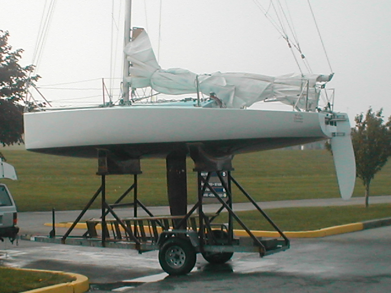
A view of the boat in 2001. This is basically what she looked like in the water in 1995. The rudder is from a J24 and was given to me.
At this point I had the following weights noted down, in Lbs. This batch of numbers is precise as determined by my weighing them.
Hull shell before anything added: 230
The structure under the cockpit floor: 18
Cockpit floor: 40
Bulkhead across the cockpit @ stn. 7. 13#
Deck: 69
Watertight bulkhead in the bow: 6
Water tank faces: 11 each
These numbers are educated estimates.
Cockpit “deck”, seat only: 10
Supporting structure for above: 5
Floatation foam under cockpit: 20
Hull fairing materials: 30
Deck fairing materials: 5
Paint: 15
Bottom paint: 10
I did not have accurate weights for the resin although I used a 5 gallon jug of WEST epoxy. Nor do I have weights for:
Flotation foam in the bow
All the cockpit floor tabbing
Deck tabbing
All the rest of the tabbing, of tanks and so on
The weight of the keel box and related attachment
The weight of the epoxy and filler used to waterproof the inside of the ballast tanks…
The weight of the boat on the crane at Goetz’s, in the summer of 1995, was 1375 pounds. This was after the keel went on but before the forward floatation foam was installed.
This included all the above but no hardware, batteries nor methods of attachment of them, any electrical or ballast system equipment. A basic boat with nothing in it.
(NOTE on the weight: Fast forward to May of 2002. The boat now weighs 1575 pounds.
This included the following things bolted onto the boat, but NOT the lifting gear itself.
Bow rail, stanchions and lifelines: 18
Jib tracks and cars: 2
Main traveler and car 2
Mast step 1
Rudder fittings on the boat 4
Mast jig for the trailer 30-obviously subtracted
Forward hatch 6
Chainplates 5
Bow float foam for which I do not have a number
Paint, I estimate 3 gallons, say 30
All the above is 98 lbs. If we call it 100 lbs. of excess stuff that was not on the boat when I weighed it at Eric’s then the net weight in May 2002 is 1475. This means, using the 1375lbs. weight from Goetz when none of this was aboard except the float foam, I have 100 lbs. I cannot account for. I have a feeling a big chunk of it is in the forward float foam and the supporting structure.)
Getting Closer to a Finished Boat

In the water for the first time in Mystic, at the Mystic Shipyard
Back to summer 1995: Even with all the work done we were only partway there. Although they are small and simple boats there is a lot needed to go onto and into these boats. In the next couple of weeks in the boatyard we figured out the locations for and then installed:
Genoa tracks, including the car movers
Mainsheet track and traveler line
All the deck hardware, blocks, pad eyes and so on
Stanchions
Compass
Bow and stern rail
Chain plates (from CAM)
Runner tangs
An electrical system, including three batteries, charge meter, switchboard, all the cabling and a volt meter.
Ballast plumbing system
Auto pilot
Speed and depth meter and the instrument
Spray hoods over the hatch. There is a little hatch on the foredeck facing aft so I can have a hood on it and keep it open at sea.
Storage bags inside the boat for all the “stuff” one has to carry
The rudder to the boat, including getting a tiller made
The frame for the sun panel
Solar panel itself
Chocks for the bowsprit pole
I also had the boat painted and put bottom paint on. We rigged the mast and boom and put it in the boat.

In the water again after 7 years on the hard, summer 2002
Time to Look at the Boat as a Whole Finished Thing
My lovely little 650 was named “S.A.I.L. for Kids” then and is now named Bushranger. The boat is 6.47m LOA, 8 feet beam, and she meets the 14-meter keel to masthead rule. The freeboards are less than the new rules require. For instance my freeboard at the bow is 30 inches while the French designed boat number 112 is 38 inches. (Think about all that added surface area and weight.) There is no escape hatch. The Melges 24 keel is fixed and there is 200 liters in the water ballast tanks. Because of the fairly flat deck and the 8-foot beam combined with the intrusion into the interior of the ballast tanks, the space inside is really quite small versus the “new” boats.

The interior of Bushranger in April 2002
Headroom was built specifically around having enough for me to just sit down, about 900 mm. (I am about 6’4″ -1.85m) The idea behind the low freeboard idea was not only reduced windage but also less weight and as it turns out more sail area. The boat meets the “10-degree heel with ballast deployed” rule. I have not fully completed the “stability” test but I have pulled the boat down so the bulb is at the water surface and, with a 4:1 Tackle to the masthead, it was still VERY hard to keep pulling. I stopped because it was late at night and I was pulling the boat down only to put the Windex and VHF antenna on.
There is only one rudder ( a gift- it was a spare J-24 rudder—cross another item off the list) on the centerline again for simplicity and reliability and because with a boat not so wide there is no need for two rudders. Again this made it easy to get parts. The rudder fittings are off-the-shelf , Schaefer stainless steel as used on production 30 footers. There is now another rudder Tom designed while I was at sea. This is about a kilo lighter but a nicer shape and a bit bigger in surface area.

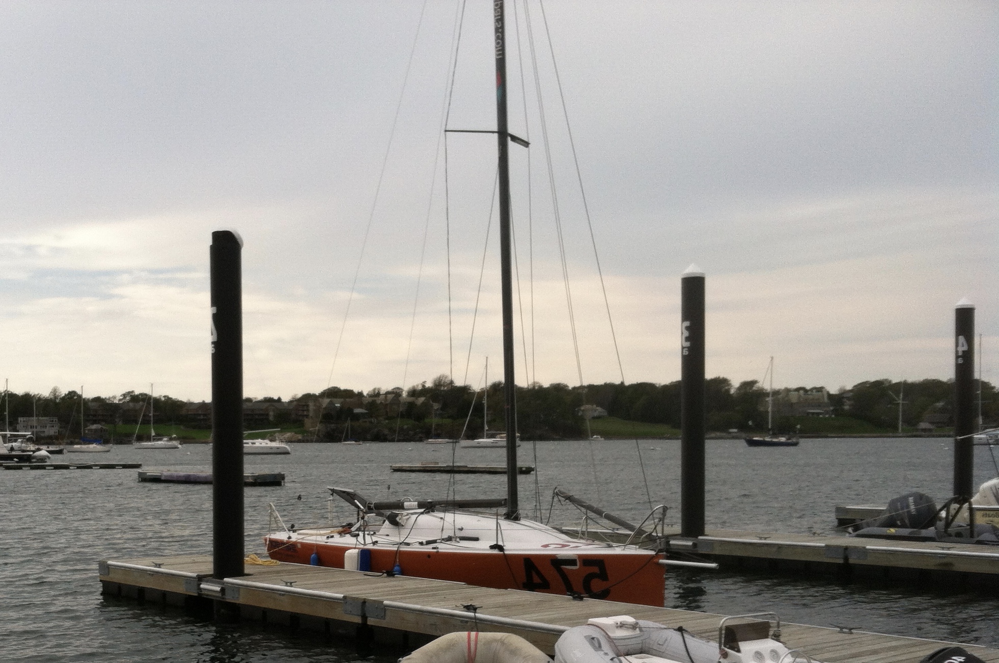
After a sail, on the trailer at Sail Newport July 2002. Probably around the time of the New England Solo Twin
There are 8 sails in total, all Hood Woven Dacron except the kites, which are Nylon. The mainsail has 5 Full Battens with Batt-car sliders, slugs in a round groove and three reefs. The carefully measured total area is 330 sq.ft. The Solent Jib is 105 sq.ft with reef, I have a high clew Jib Topsail, about 115 sq.ft. and 2 storm sails in heavy Dacron. The storm staysail has a reef and the trysail is orange. The kites are a 600sq.ft. Masthead kite, a 326 sq.ft. Fractional kite and a 318 sq.ft. flat genniker on a roller. Although built in 1995 the sails have very little use. The main and jib have the most use and then the big kite.
It would be possible to get an 800 sq.ft (or even larger) spin on the 7 foot pole. The ISP is about 39 feet so using a 41 foot luff length and a 165% of JC girth kite it could be about 850 or so. Considering the less wetted surface my boat has compared to the wide boats I think this is more than enough. It would be possible to have a 1,000 sq.ft. kite with the 3m pole.
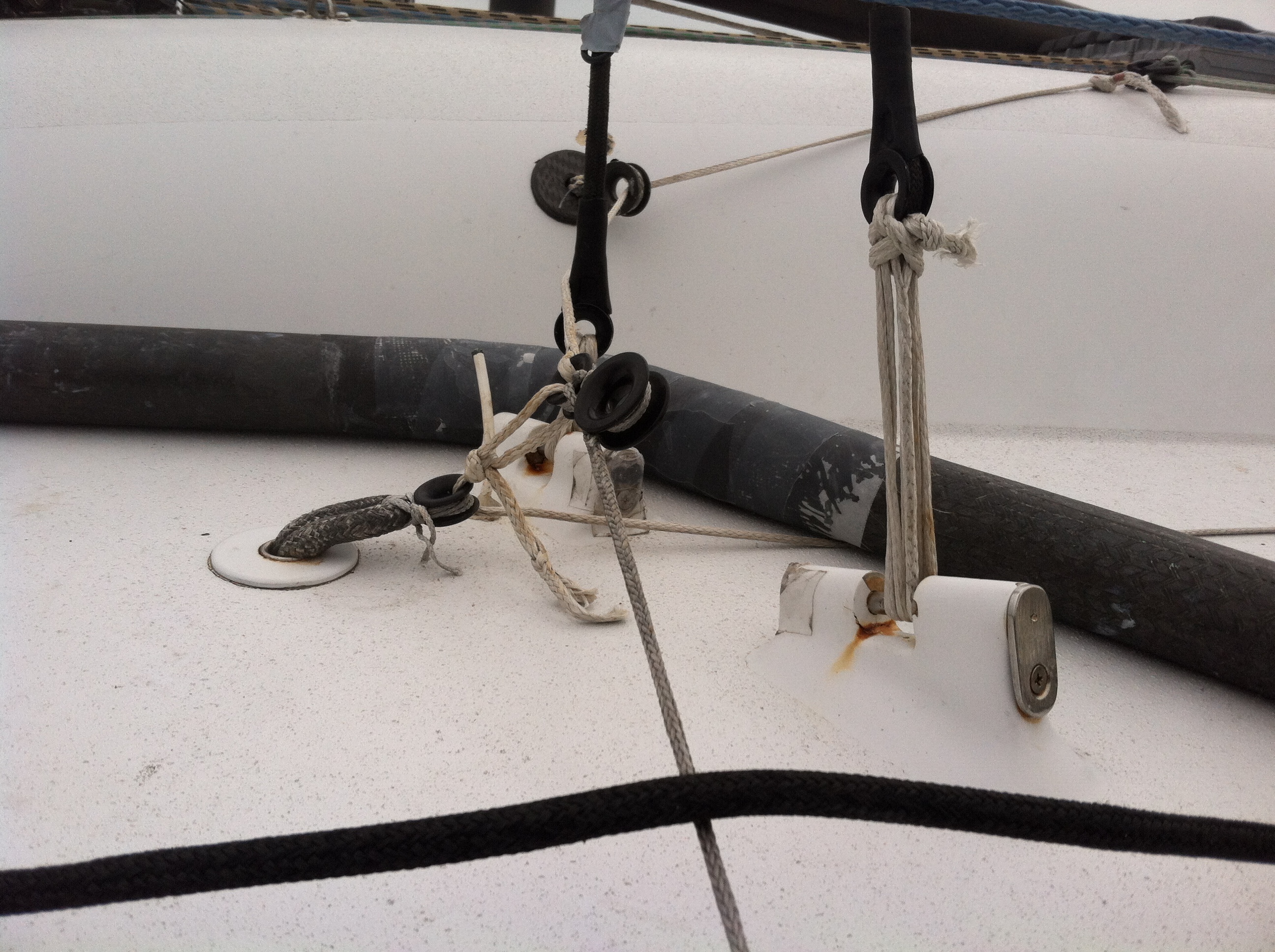
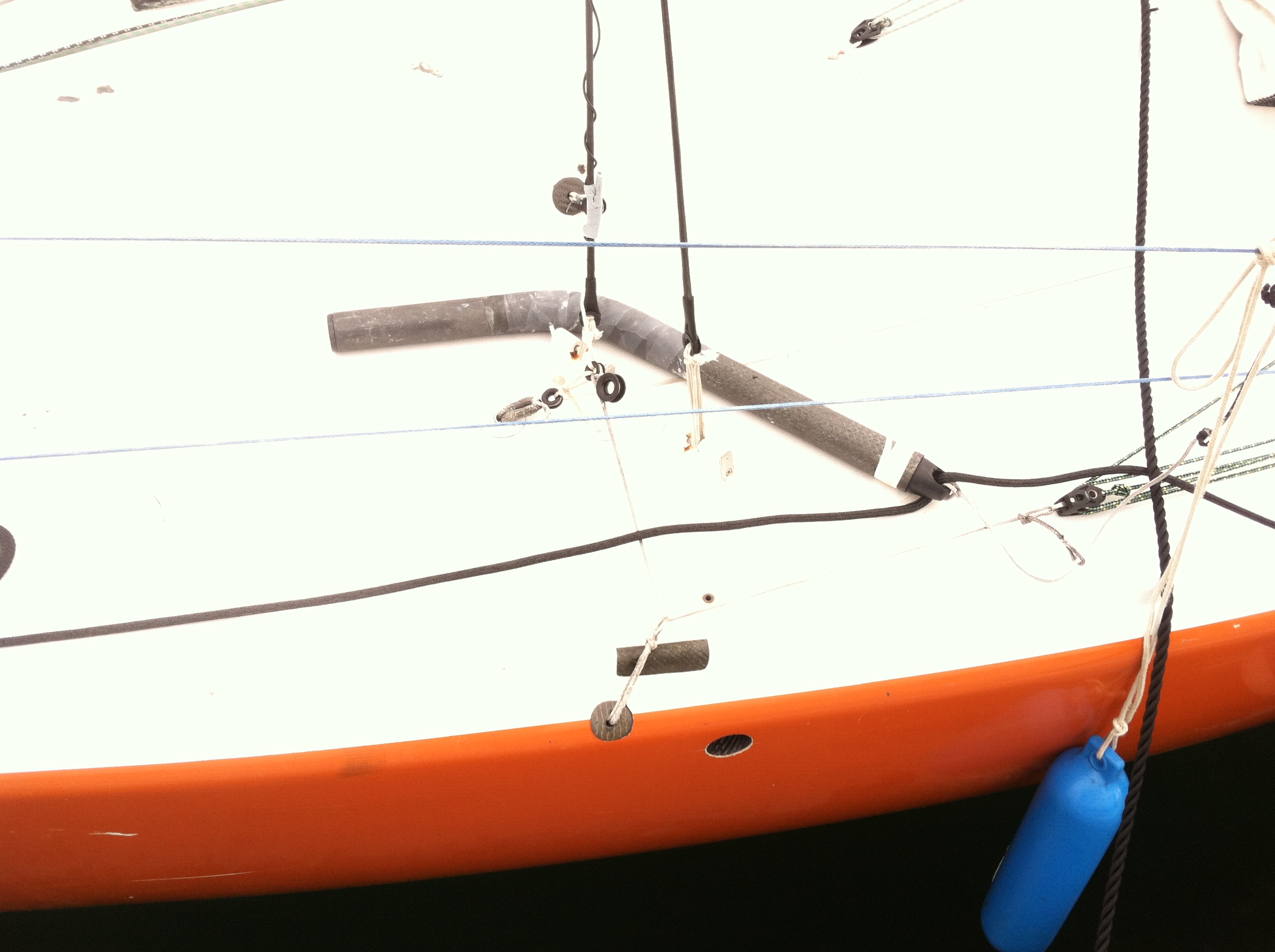
There are just 2 Lewmar winches, Lewmar deck tracks, the jib sheet cars are adjustable, Lewmar mainsheet track, mast base blocks etc. with some newer Harken blocks, Lewmar and Spinlock Jambers. All the cordage for sailing like the sheets, guys, halyards is either Kevlar or Vectran covered in polyester. At the moment I have a German AC double-ended main sheet system and a 2:1 with 6:1 fine tune on the jib sheets, so I can adjust the jib sheet from the high side while steering, without a winch. There is also a 60 watt Solar panel.
The Inside of the Boat

A view of the interior in April 2001. I had started on the “refit” as the bare wood around the port aft tank hatch indicates
Well, what is to be said for a Mini interior? Apart from the fact it is on the inside, not much. It is white, there are storage bags, an electric panel, battery and enough room to lie down and snooze. I have done all of this and cooked, if not a meal at least re-fueled enough to keep going. There is VHF radio with the correct antenna, Navico pilot, Navico speed and depth meter, Sea Swing stove, ballast/bilge pumps, spare bilge pumps. One Danforth anchor, chain & rode, safety jack lines on the deck and a Compass.

Picture of the interior taken April 2001. Very much the same as I left her after I arrived back from my aborted attempt to get to France. Lots of strong memories. I have the log and a diary too…
Most of the other safety stuff expires, like flares, but I have enough current safety gear for sailing off Newport. There is also a 406 EPIRB but, like much of this stuff, for the cost to replace the battery and the cost of re-registering it today, one can go out and get a new one. Boat is also set up with a center lift sling so it can be pulled out anywhere you can get a 1,000kg crane along side.

On the crane at Sail Newport with yet another helper, Rich Moody
All in all the boat is very strong, simple, fast to sail up to speed and watertight. I have sailed her at over 10 kts. in 9-12 kts. of wind at 90 degrees apparent with the masthead kite up (and full main) with one crew and the boat is a joy to steer. In another (double-handed) race I have sailed at 7-7.5 plus knots with a full main and fractional kite in 5-8 kts of wind and fairly flatt’ish water at about 45-50 degrees apparent wind angle. I have sailed the boat upwind, solo, in 18-20kts apparent with one reef in the main, no ballast in and steering with a piece of string tied from the tiller to the life lines, this for over an hour, while I had a rest and looked around.

After sailing, July 2002. The boat has the “proper” rudder shipped.
It was very interesting to me to have in the loft (I was working for Hood Sailmakers at the time) some sails from a slightly later French design boat, #112. I discovered (by laying the two sails on top of each other) that my mainsail plan gives the same area with 500mm more hoist on the main. This is another reason for the low freeboard and the flat deck when you have a 14 meter rule. With the narrower boat I know for sure I have less wetted surface and a lot less drag from all those foils dragging through the water. So the same waterline and same sail area combined with less wetted surface is a pretty good combination for speed in my mind.

Our first sail late in the afternoon. Scott Bradford assisting and checking the spar. There are few things I have experienced that are as satisfying as sailing a boat that you have (largely) built yourself.
I was an accepted entry in the 1995 race under the name S.A.I.L. for kids, USA 50650. I left New York en route to France to start the race but was delayed by avoiding hurricanes and then finally returned to NY. I had realized I was, to too great an extent, still building the boat. True it was built and sailing but I had too little time in the boat, too little time after I would arrive in France and overall I was totally pooped.

Sea trials one day in Summer 1995. A fresh North Westerly-A good time to test out the small sails. Gordo Wagner assisting at the mast.
This was in September 1995. I am fully aware of the smallness of these boats when faced with really hard weather. Solo in the fall in the North Atlantic, with no other boats around in a boat you have only just (almost) finished building did not excite me too much. It was with a really heavy heart that I turned tail and returned to NY.

A “press picture” of me, along side the docks at South Street Seaport, NYC a day or two prior to departing for France, Sept 1995. Picture Don Miller www.donmillerphotography.com
The S.A.I.L. for Kids name was the plan I had to sail the race, have school kids follow the race from the Argos positions and also to follow the school lessons I had prepared for the purpose. Even before 1992 this was being done especially with the BOC. I thought the Mini would be a good boat to follow because it did not take so long and was across the Atlantic, an ocean that most American school kids know a little bit about. When I came back I called the Mini Class and arranged to get all the press releases and the positions every day via fax. I then called all the schools who had subscribed and told them what happened so they could still follow the race even though I would not be in it. Or I would return the money. All the schools said their kids were so excited they would follow the race without me and so I followed the ’95 race as closely as if I HAD been in it. As it turned out it was long, light air race. This really annoys me because I think my boat would have had the performance to do well. Oh well, life is an imperfect arrangement.

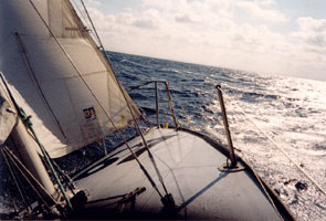
Underway outbound New York Harbor bound towards France. The books and stories are right. The emotional energy runs at full flood. Picture Don Miller www.donmillerphotography.com
Since I returned from my abortive effort to sail in the Mini-Transat the boat has been out of the water , almost 7 years. Then, in the winter of 2002, I did a pretty big overhaul of the boat, changing things I did not like and redoing things that were done in a hurry towards the end as I prepared to leave for France in Sept 95. I have just about gotten over the disappointment of expending such energy and then not getting to the race. The boat is for sale. It is in Newport RI, where I now live. For someone who is interested in a boat that is not the same as all the rest it is a boat that should be looked at. I am in no particular hurry to sell in that I do not need the money to pay the bank or my aunt or something like this but it is time to move on to the next adventure.
I think it is a great boat with excellent potential especially in the new course across the ITCZ with the light and shifty air. I see that for the 2013 race it is back to the Carib. Island of Guadeloupe.

You are single handed on the boat, but no one does these things alone.