
One of the great aspects of my life is I get to wander around boat yards and so see lots of really interesting and innovative things to do with boats. Very kid in a candy store stuff. A couple of days ago I was at the Hinckley/Hunt marina complex in Portsmouth RI when I came across two Hall technicians prepping a Carbon mast to be returned to its boat, a 90 foot Gunboat catamaran.
Hall Spars has long been a leader in the construction of Carbon fiber masts. Brothers Ben and Eric Hall have been building spars for pushing 40 years and carbon masts, booms, kite poles and other carbon bits for probably 25 plus years. This brief post shows some pictures of parts of the mast and some commentary from me. Enjoy.
This first image, below, is of the bottom of the mast. The rig is a partial wing mast (NOT a wing sail), which means that it is perhaps 700 mm long (fore and aft-Compare with the ladder or my coffee cup on the ladder) and is much more wing shaped, albeit thicker, as wings go, than a conventional spar.

There are a number of reasons for using a wing shaped mast on a fast boat, not the least of which is to reduce drag as the airflow begins to pass over the sail. The drag from conventional shaped, (roughly oval in cross section) adds up when you do the math to sum the cross sectional frontal area exposed to the wind. An additional benefit of wing masts is there is a lot less standing rigging required to hold the mast up-This has long been a benefit of multihulls because of the wide staying base.
A wide staying base reduces the loads on the mast, and also the amount of rigging needed to keep it up. With the elimination of multiple sets of spreaders, and intricate standing rigging, the mast can be this wing shape.
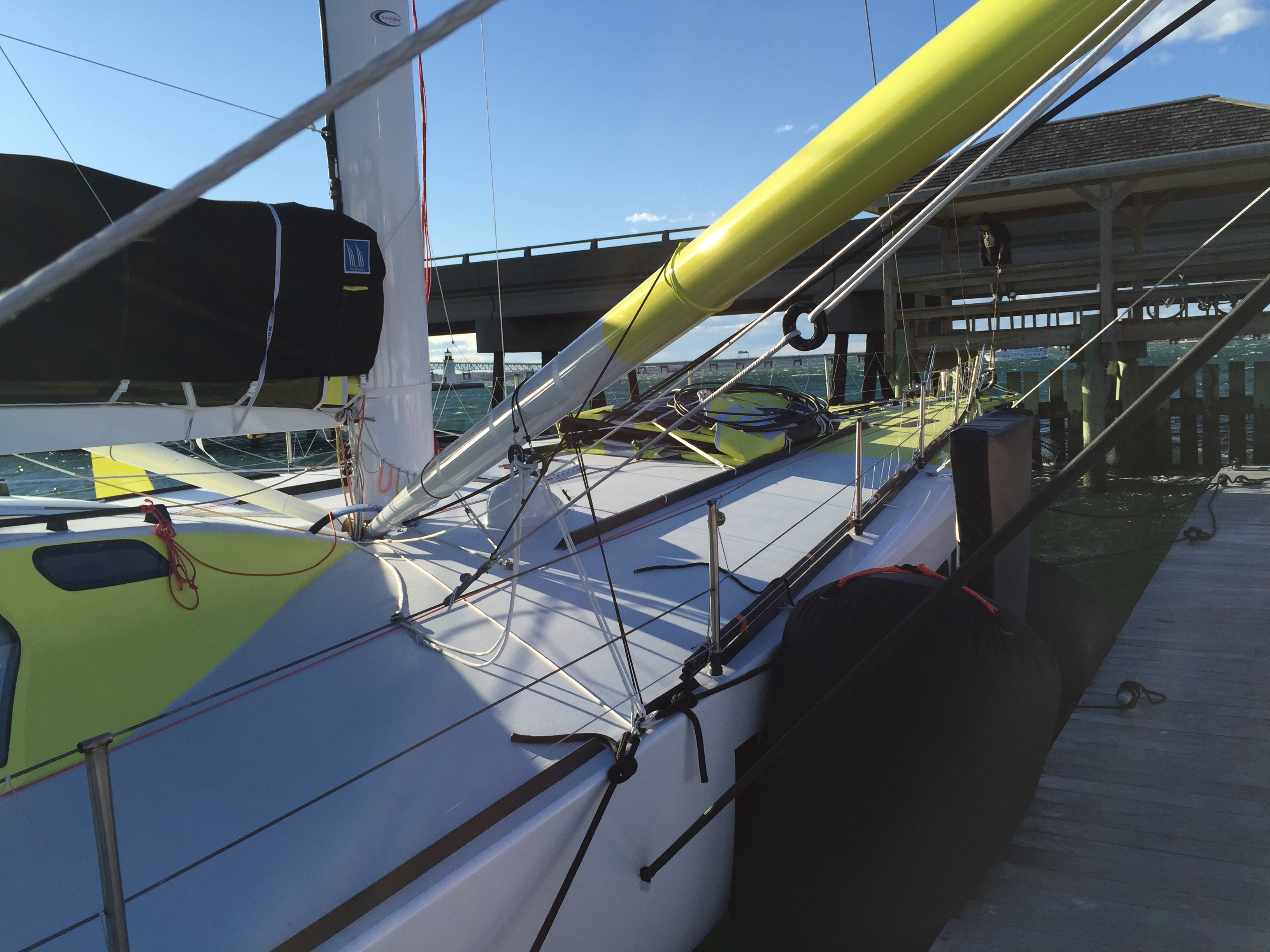
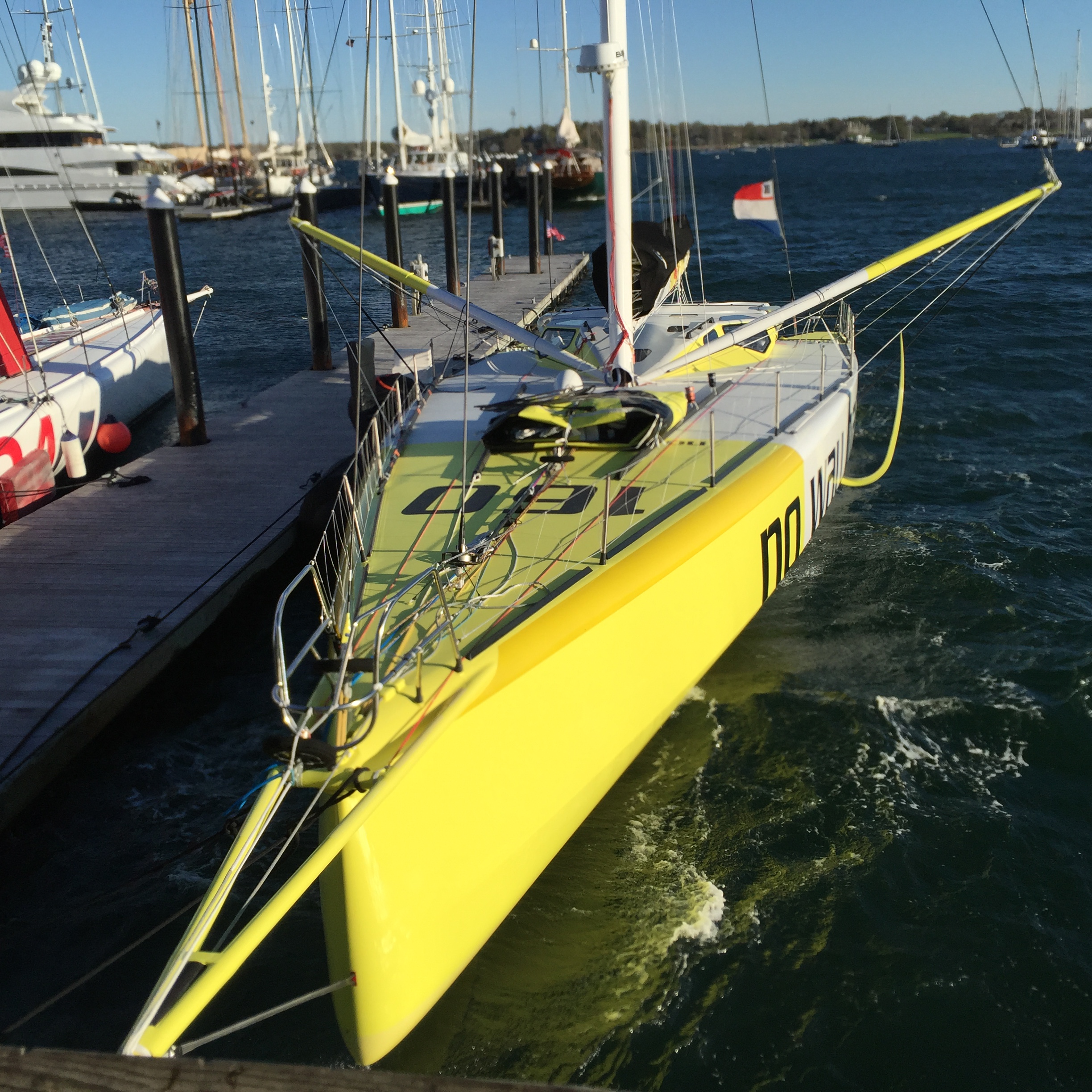
Today, composite standing rigging is certainly lighter and stronger than any metal rigging, but composite standing rigging is thicker in cross section, so having less of it is a big plus. The image below is of the ‘bobstay’ securing the top of the deck spreaders to the hull on No way out, the latest IMOCA 60 from VPLP/Verdier. The acute angle demands stronger, so thicker material, but you get the idea.
The bobstay, is secured to the hull in some invisible fashion, below. Notice that all of this is so the boat can have its own partial wing mast, or vice versa…
Finally the drag goes up exponentially with the speed, so a cat or tri (Like Spindrift, shown in the featured image) is incorporated into the sail area and sail shape for considerations of sail shape.
The facility of wide shroud base has transitioned into the IMOCA 60 boats, (seen below is ‘No way out’) such as those in the Vendee Globe presently underway.
This latest generation IMOCA 60 has the now common deck spreaders and wing section mast. The spreaders are to get a wide shroud base, to minimize the compression on the spar so it can be a bit lighter. Many, many Excel spreadsheet Cells were sacrificed in figuring out the cost benefit of this arrangement.
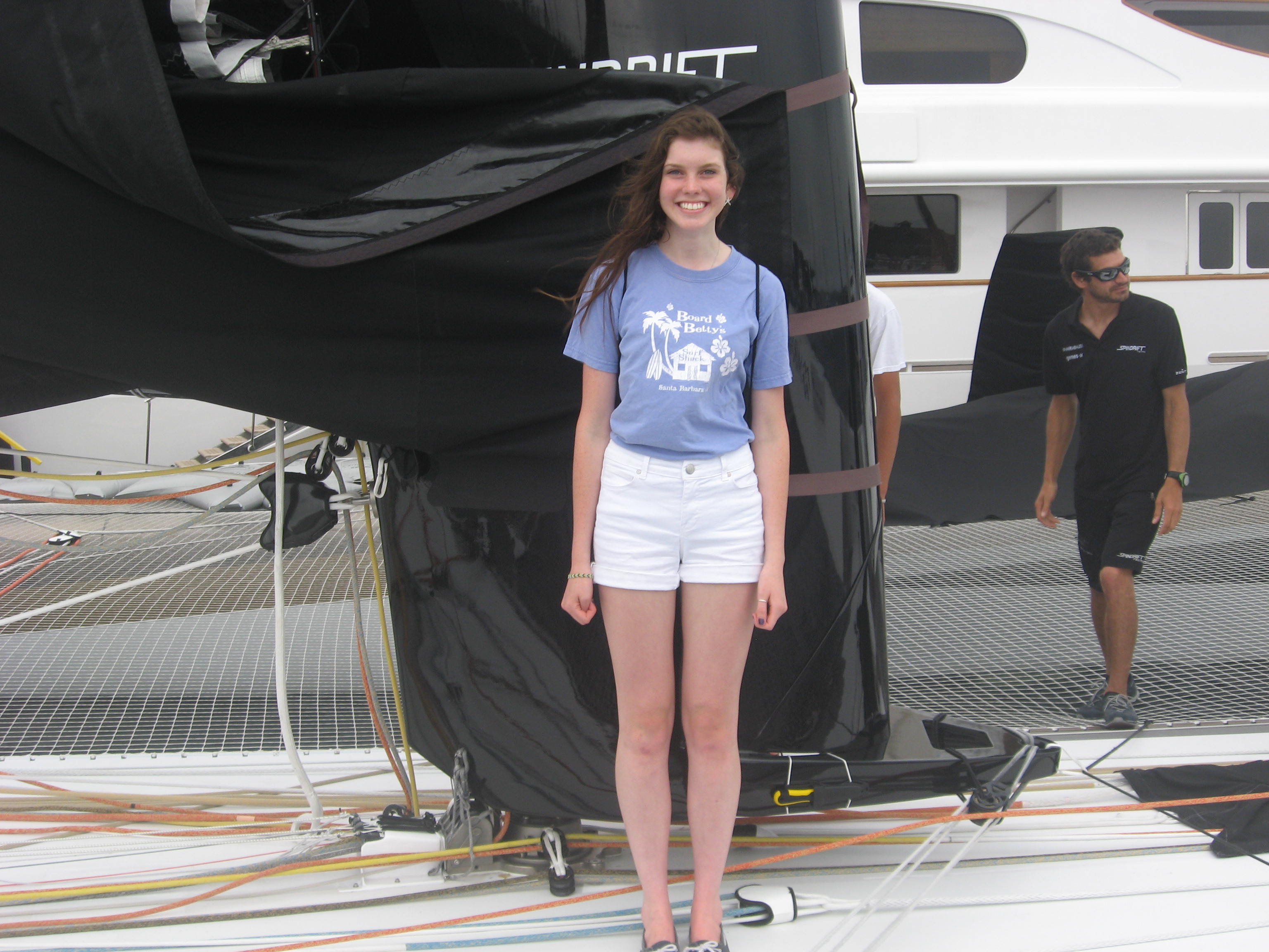
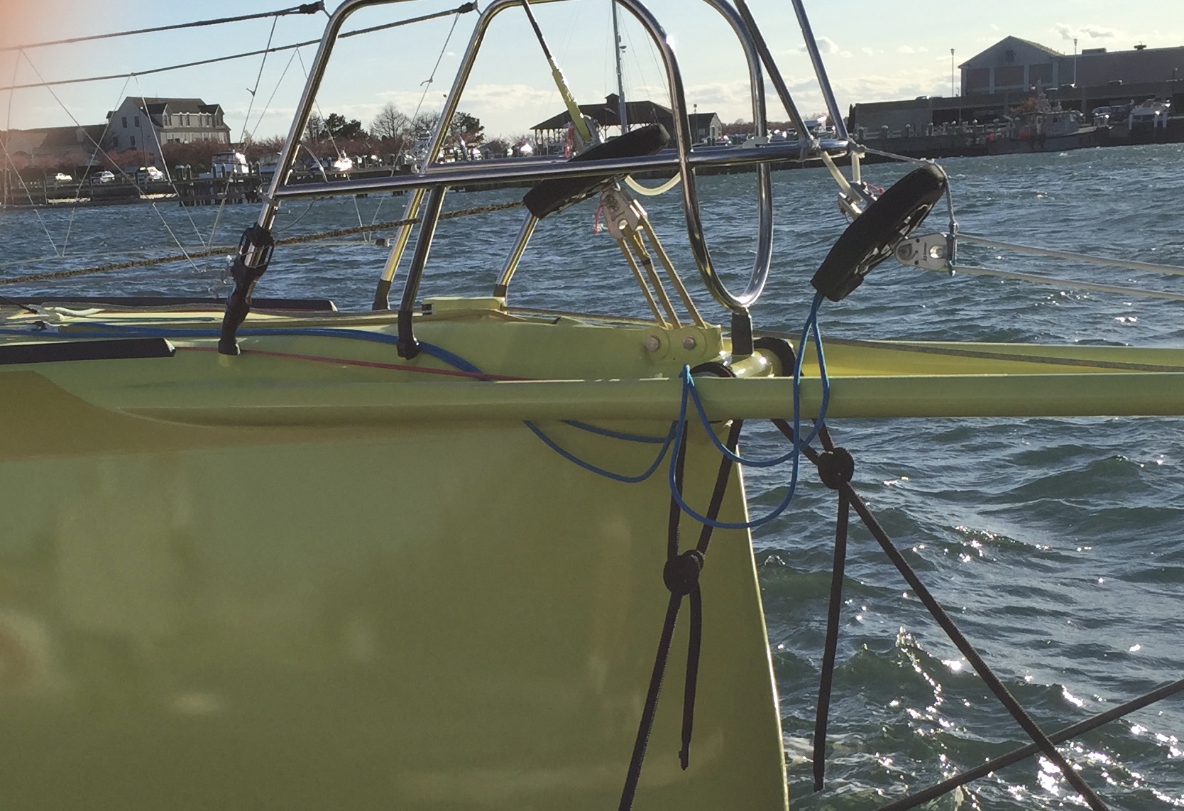
The variations in the size of wing masts are as varied as the boats themselves, as this picture below, of Spindrift, shows. (Spindrift Racing was kind enough to let me have some of the Prout Sailing Team visit Spindrift a couple of years ago.) On the forward side of the mast, at the base, you can see the rotating quadrant with tackle attached. See too, the knife in the yellow sheath, just next to Julia’s left calf…..
Back to the Gunboat mast.
Because it is a wing mast, it is deck stepped so it can be rotated. (Or perhaps it is the other way around. It is stepped on deck so it CAN BE a wing mast). To achieve this rotational ability, there are two unique details. The bronze colored circle in the middle is the fitting, slightly concave, which lands on top of its mate on the mast step, on the boat. It is basically a bearing surface for the mast to sit on, so it can rotate.
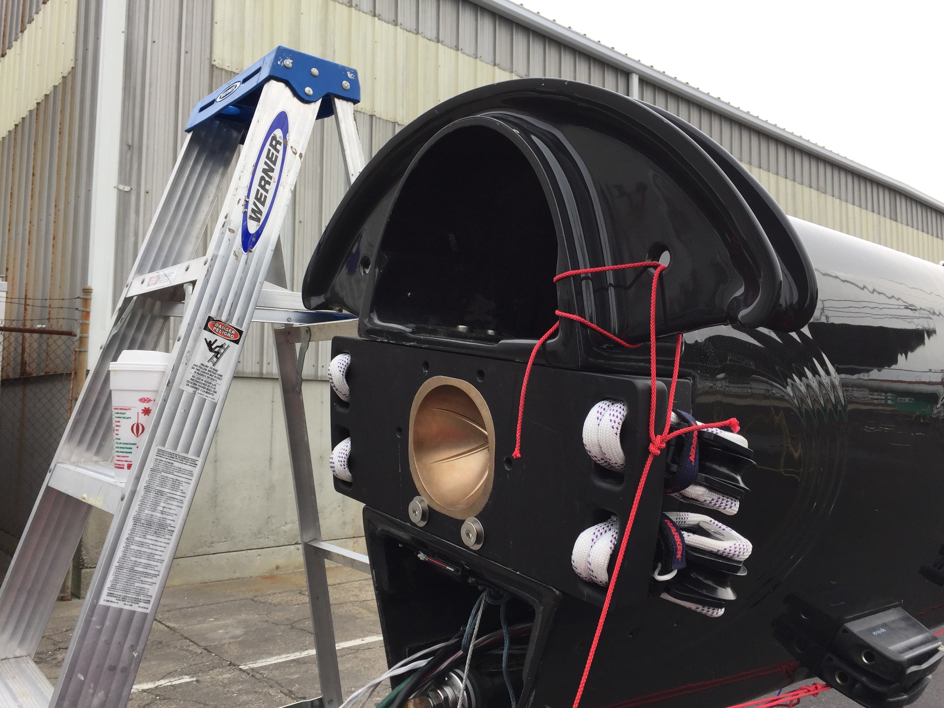
The half circle looking part is on the forward side of the mast. It is, and so acts like, a quadrant, in a wheel steering system providing a lever arm to move the spar. There are control lines mounted to it and when actuated, these lines can turn the mast thru, what looks like 90 degrees, but is probably only 45 degrees, either side of fore and aft, in practice. You can see these more clearly in the Spindrift images, above.
This closer detail shows a remarkable piece of carbon detailing and finish work. Smooth, shiny and undoubtedly strong. It is as much a work of artisan craftsmanship as an engineering part for a 90-foot high-speed sailboat.
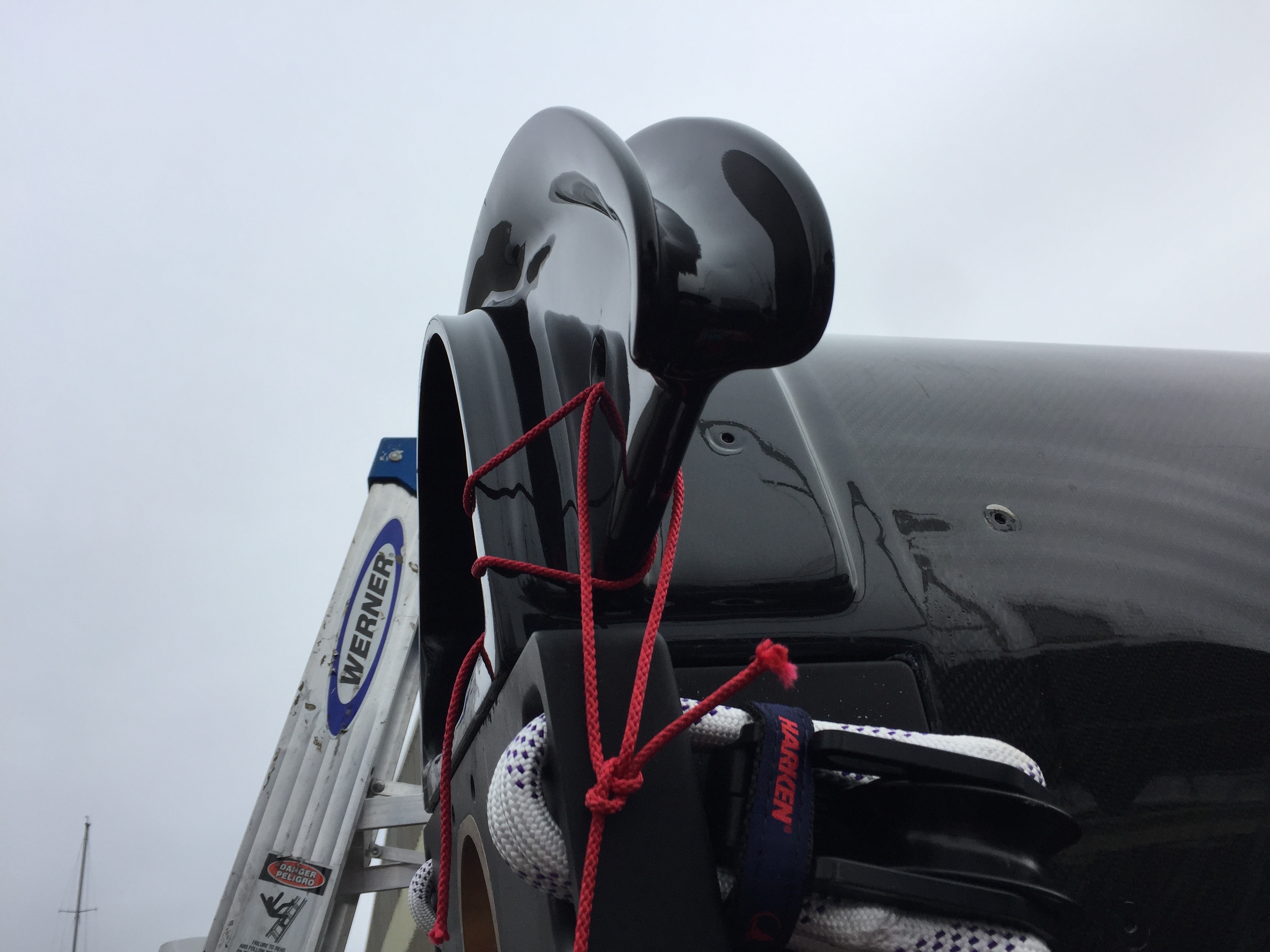
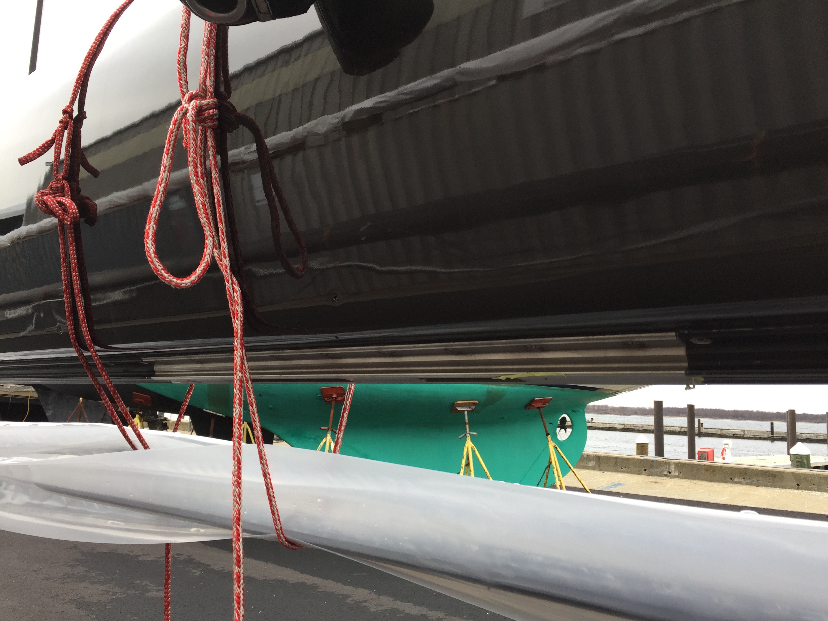
Built into the base of the mast is a detail to accept the halyard turning blocks. This design is necessary because the (aft side of the) mast moves thru, perhaps 12-18 inches when being rotated, so incorporating the blocks mounted onto the mast eliminates the traditional idea of mounting them to the deck with big pad eyes thru bolted.
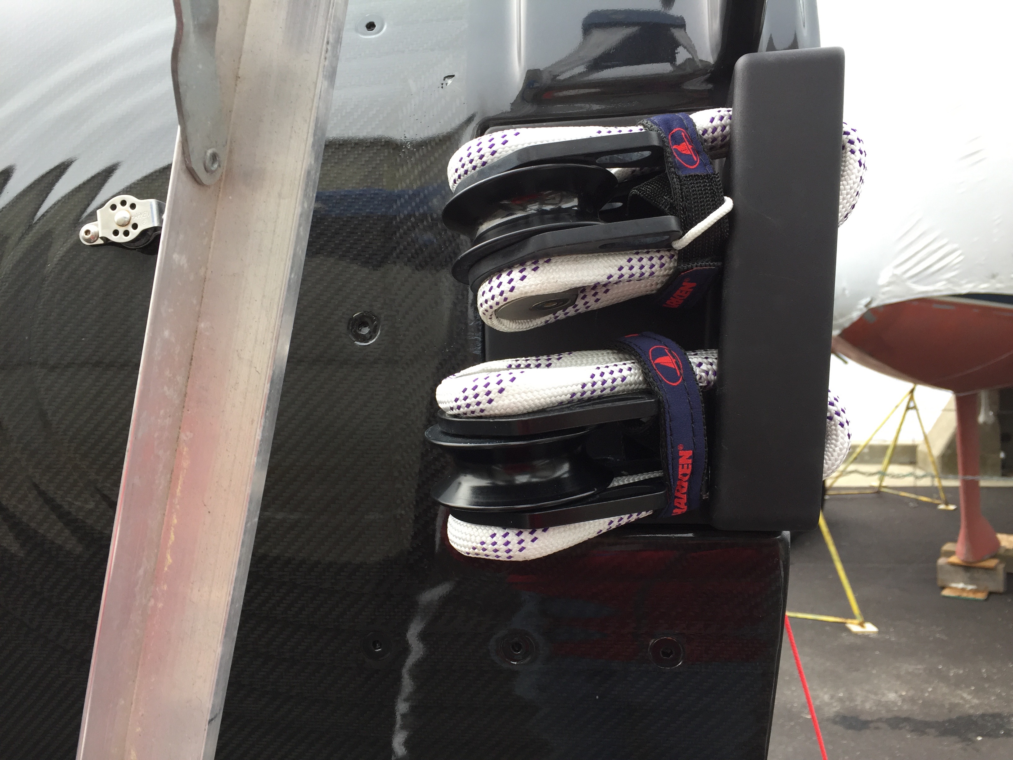
This traditional method would not be very successful in any event because the halyard’s lead out of the mast would be moving all over the place as the mast rotates. In keeping with the proliferation of using cordage in lieu of metal for securing things to the boat, these Harken blocks are looped onto the mast with large diameter spectra. The Harken Velcro straps stop the loop from separating when there is no load on the block. The little piece of light line is probably to keep the Velcro attached to the boat when working on the block
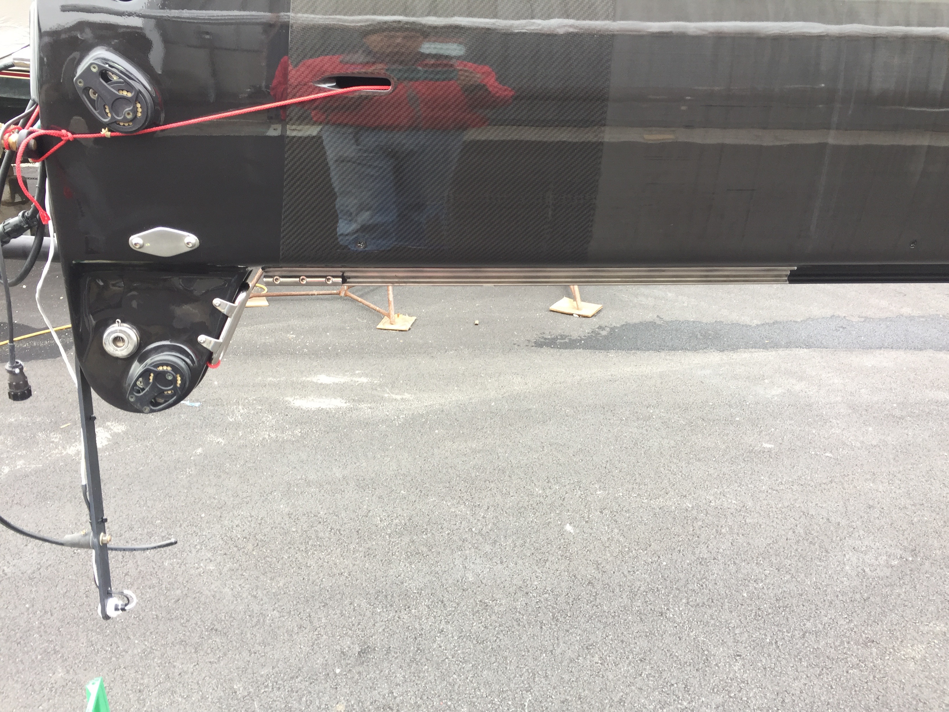
At the loads the sails on these boats generate the engineers must consider the transfer of this load thru the (main) sail’s leech to the mast track. In this picture, a section of track is the pewter colored piece on the aft side, the bottom, of the of the mast in the image. The loads on this boat, when sailing full speed, close to the wind, with a fully hoisted main are considerable. Bear in mind that a 90 foot cat, particularly a light fast one, generates the kinds of sail loads roughly equal to a 140-150 foot monohull
And just as much load is generated when reefed. This next image shows the beefy metal (I did not ask what) at the reefs too. The luff track/batten car slider system is suitably large Ronstan ball bearing equipment. This construction detailing on the spar of course requires considerable communications between the Sailmakers and the mast builders as to where the head of the sail will land when the sail is reefed.
Another detail to do with the huge loads on this (these) boat (s) is that they do not use ‘conventional’ jib halyards & furlers but rather the foresails are on ‘free luff’ furlers. These furlers have become pretty commonplace on high test boats from Class 40’s to Ultimate trimarans, like Spindrift, above.The dead weight of the sail and furler combination is lighter than a conventional aluminum section (or Carbon sections on bigger boats) and can offer the option, quite often exercised of removing the sail and stay completely. The benefit to this of course is to, again, reduce drag and weight aloft and, incidentally, improve stability. The concept and equipment for this kind of free luff furler comes from the reaching Genoas used on furlers for the solo offshore race boats for perhaps the past 20 plus years that has now trickled down to all manner of boats. In order for the loads to be accommodated, the sails/stays are secured by halyard locks. The idea of halyard locks has been around for a while–many smaller boats, Finns, Etchells, and so on have halyard locks, for the mainsail at least, and have had for years.
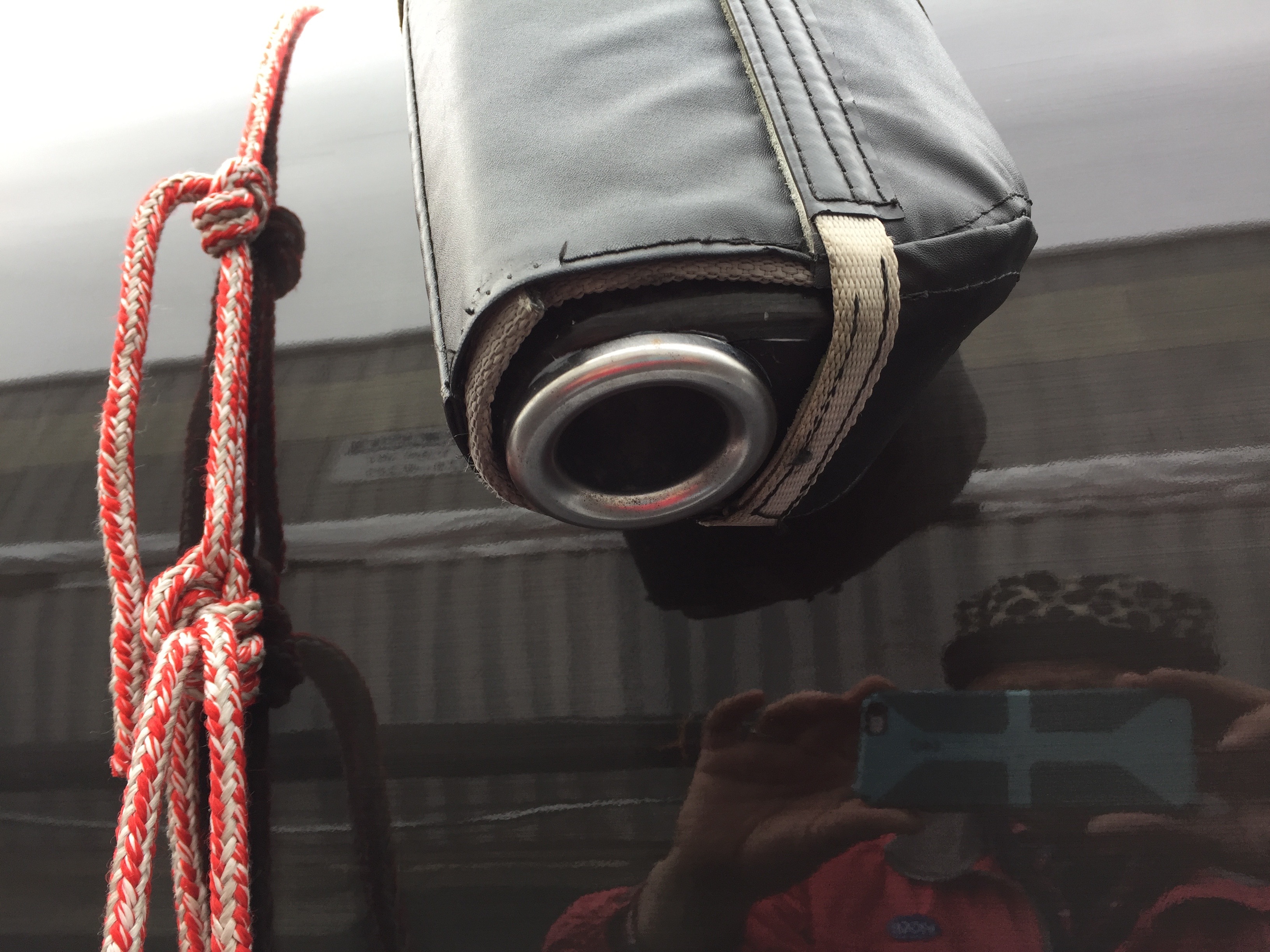
The contemporary high-load halyard lock is a bit more sophisticated though. The rigging of this halyard lock and free luff sail arrangement involves a ‘stay’of a lightweight composite fiber manufactured for the purpose, being captured inside a luff tape on the jib and secured to the head and tack of the sail.This idea is basically like the luff-wire in the jib of a 420-dinghy jib for instance. The rolled up sail is hoisted on a ‘halyard’ that is really just a length of line, robust enough, to hoist the sail and, when hoisted, the top of the stay is introduced into this metal lock and is thus held in place with no load on the ‘halyard’. The lock is held to the suitably reinforced part of the mast with Spectra loops, seen below.

This reduces weight in the mast because the sheave area does not have to be so strong as to resist the halyard tension, rotating over the sheave at about a 160 degree turn and the (hoisting) sheave itself can be much smaller, just big enough to sustain the loads of pulling the sail up. This absence of halyard load reduces the compression on the spar,(cf halyard loads in previous sentence) another element contributing to the weight (savings) in the mast. No (conventional) halyard means fewer blocks at the base of the mast, or winches and clutches on the mast and so on. The lock is probably one of the few metal parts on this mast. The lock hardware thus has a padded jacket around it to protect the (beautiful) carbon work the mast represents.
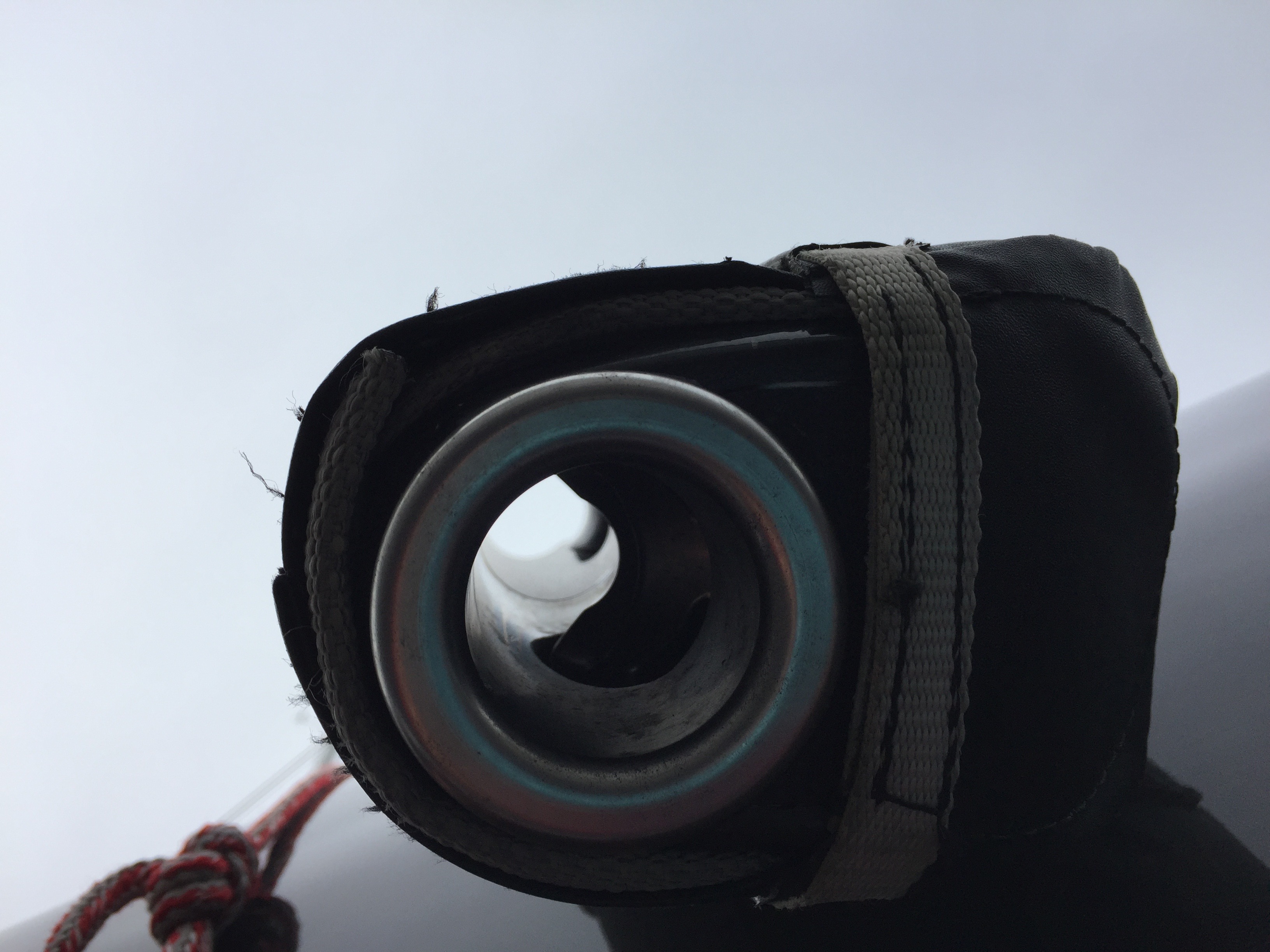
The above view is up through the tunnel which the part to be locked, the top of the stay, fits.
The stay is tensioned by some combination of tackle, winch or hydraulics as seen on, again, the IMOCA 60, No Way Out.
As noted, wing masts have a lot less standing rigging that a conventional mast, but they are not without some rigging. The picture below shows the additional layers of carbon laminated in and around where the spreaders pass thru the mast. The technique the Hall folks use is a layup over a mandrel, so the outside of the mast shows all the effort put into the work by the technicians actually laying the fibers onto the spar. Truly, art meets science. The shiny-ness of the mast is probably due to a clear coat paint job.

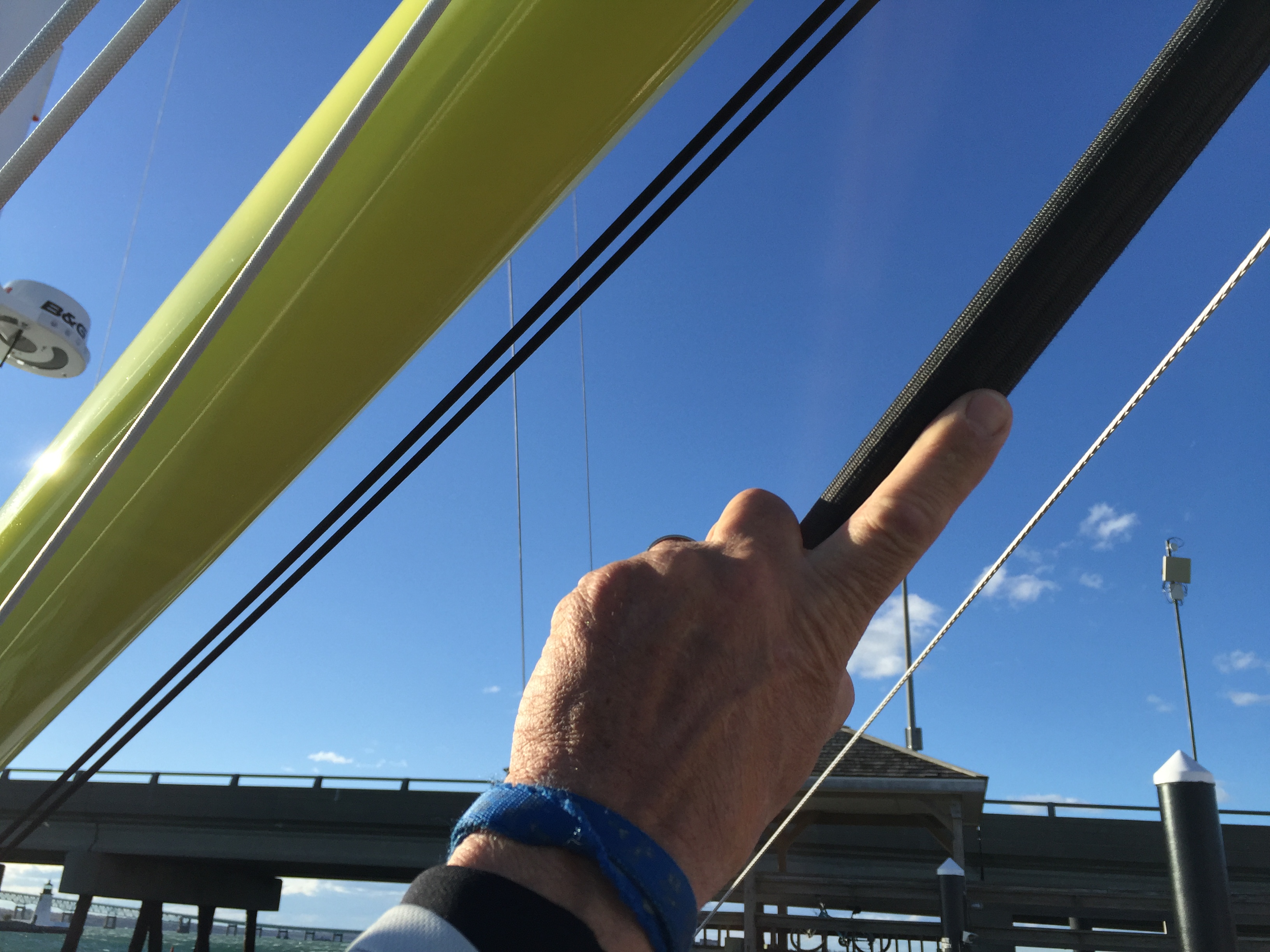
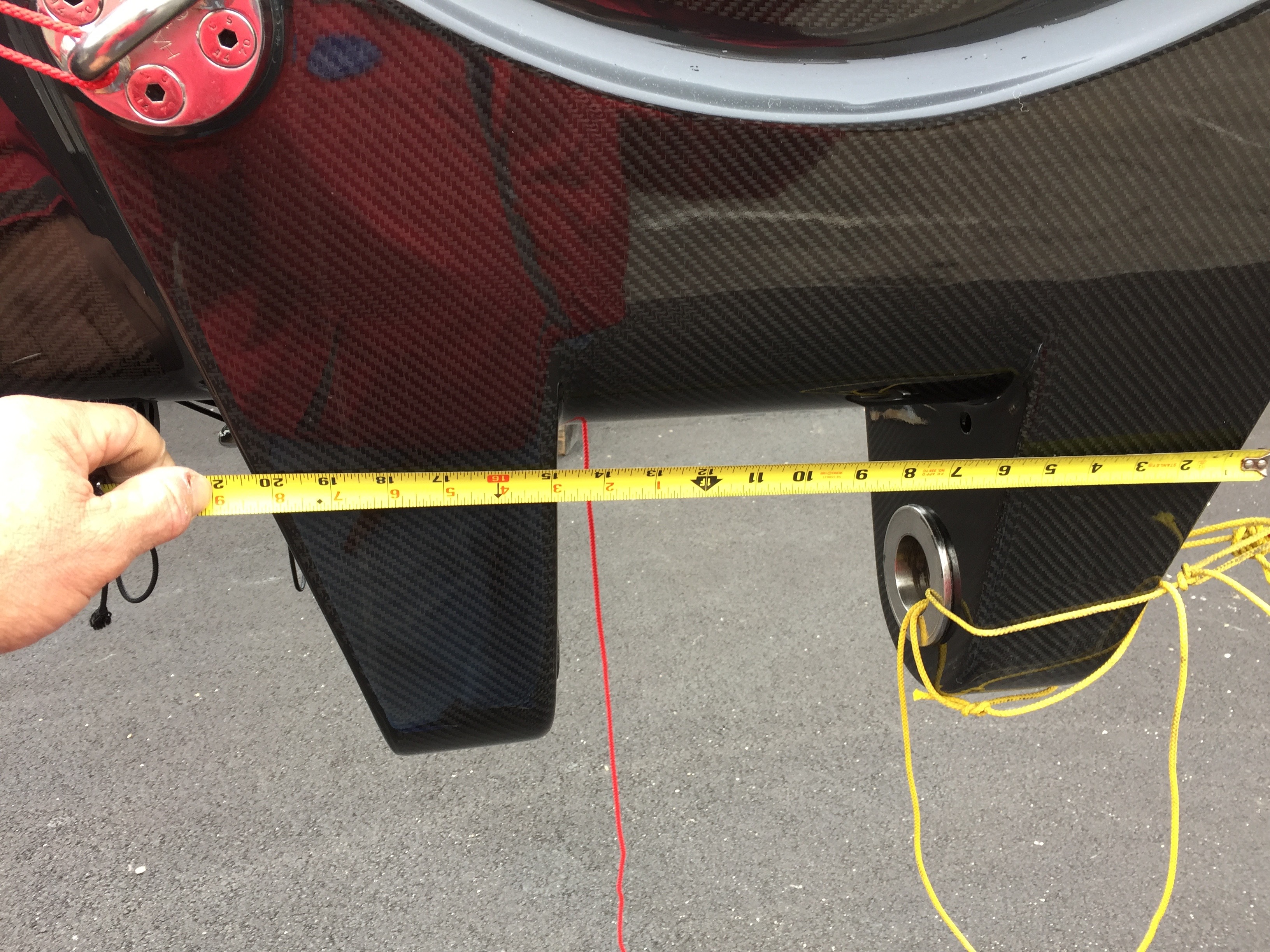
The engineering of these masts is pretty complex and must take into account all manner of multi-directional loads, both static AND dynamic and peak loads, as when sailing into the back-side of a wave at 30-35 knots and slowing down rapidly to 20 knots or less. The composite lay up for the boat’s gooseneck must withstand this loading and have a suitable safety factor to boot. This probably accounts for the size of the gooseneck. My thumb is at 21 inches.
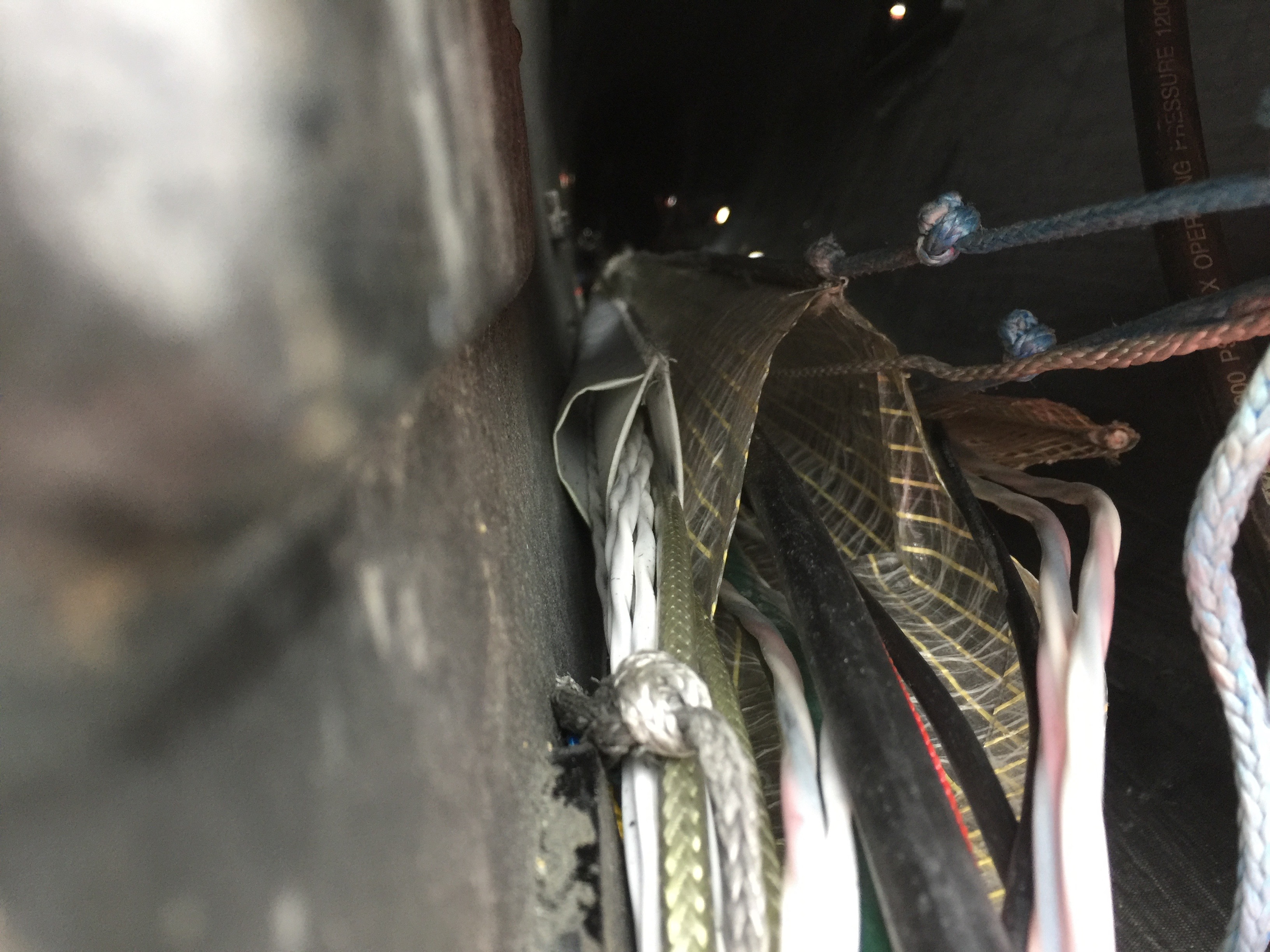
A proper seagoing mast ought to have a tunnel inside the spar to run the cabling for all the electronic and electric stuff. An innovative variation on the typical round tube held to the inside of the mast is this sheath fabricated from some light sailcloth. All the cabling is captive inside this sheath. It is held in place and tensioned by, at the bottom, the piece of lightweight Spectra, the blue colored one. The reddish piece of Spectra is probably mouse line for installing and removing cabling.
Certainly not all of us have the means to own and operate a gunboat 90, but as noted above, hanging around in boat yards is, for many water rats, a fine thing to do.
Feature image Spindrift Racing, 30 meter Trimaran.
Picture courtesy Spindrift racing