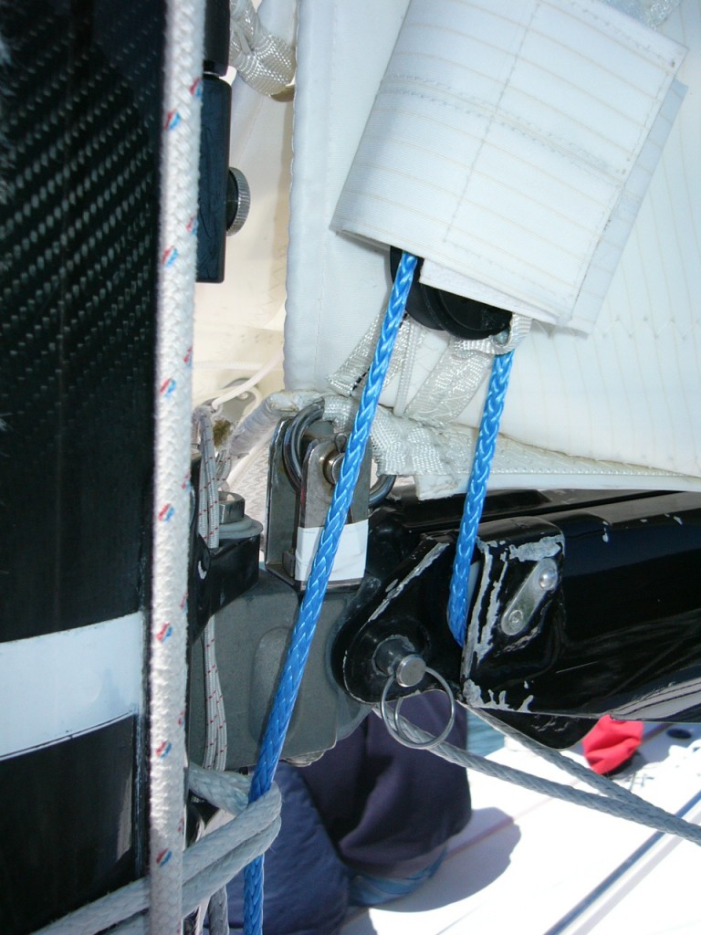
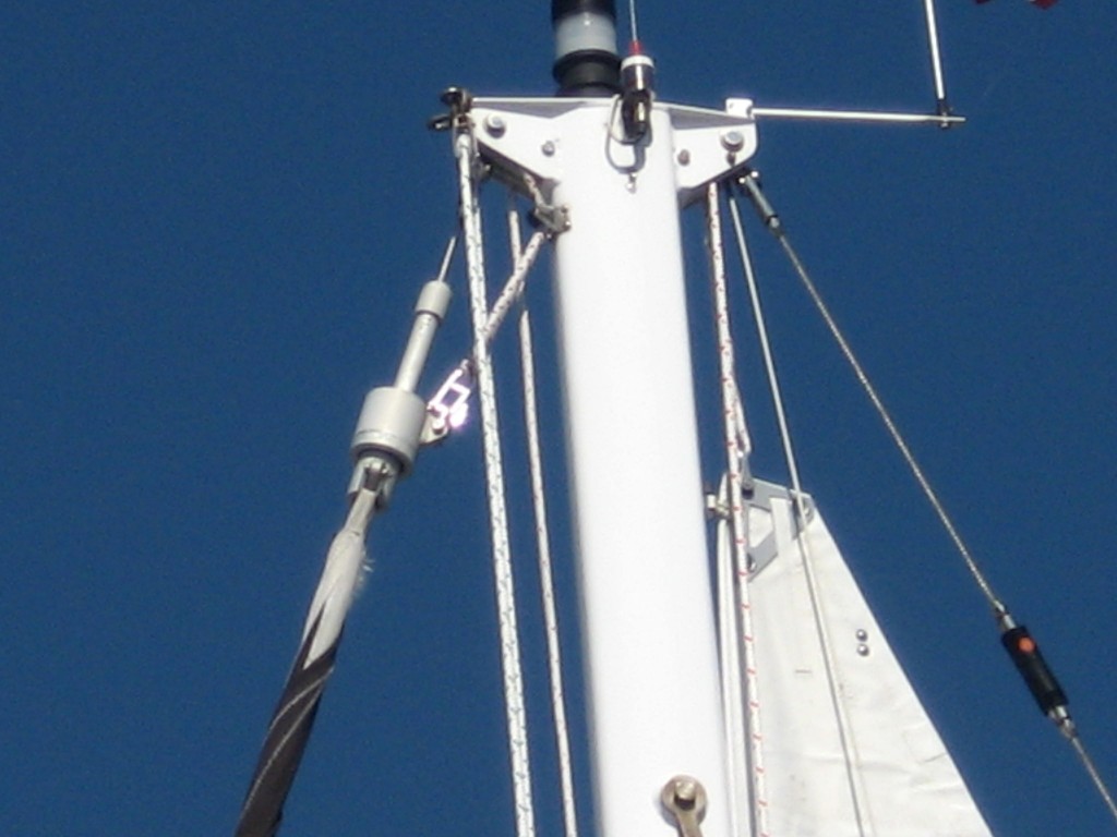
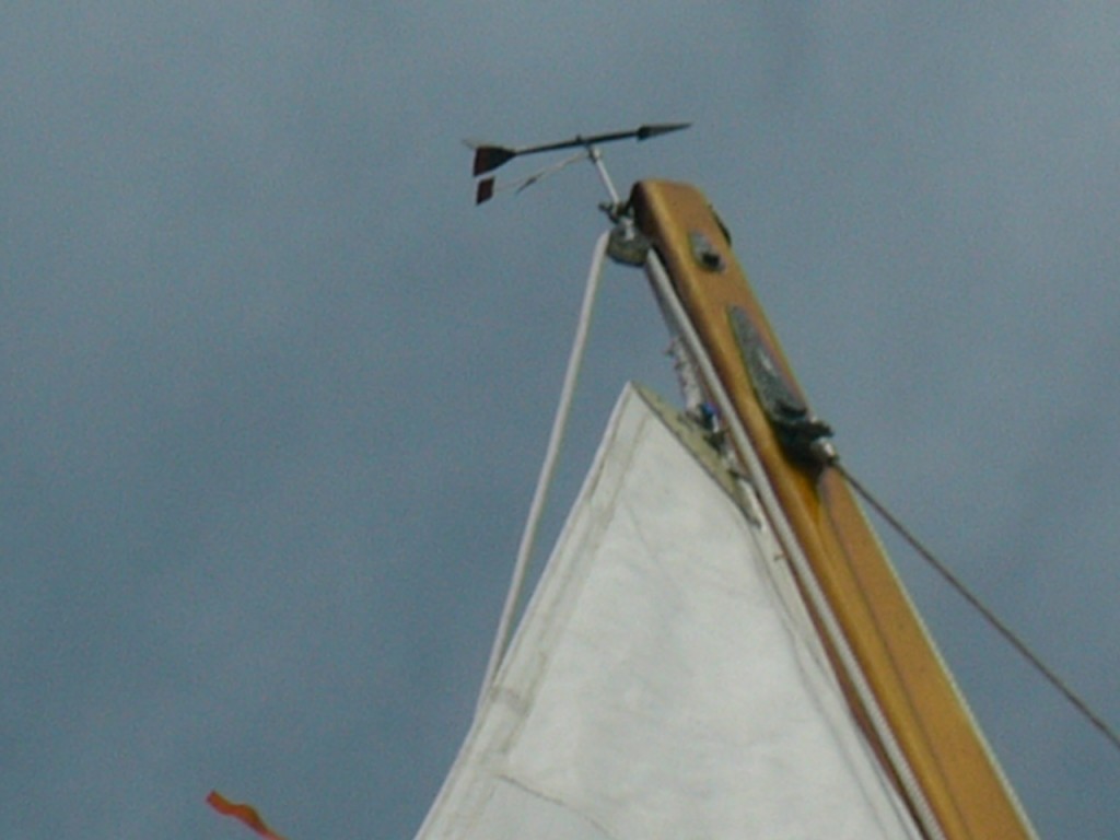
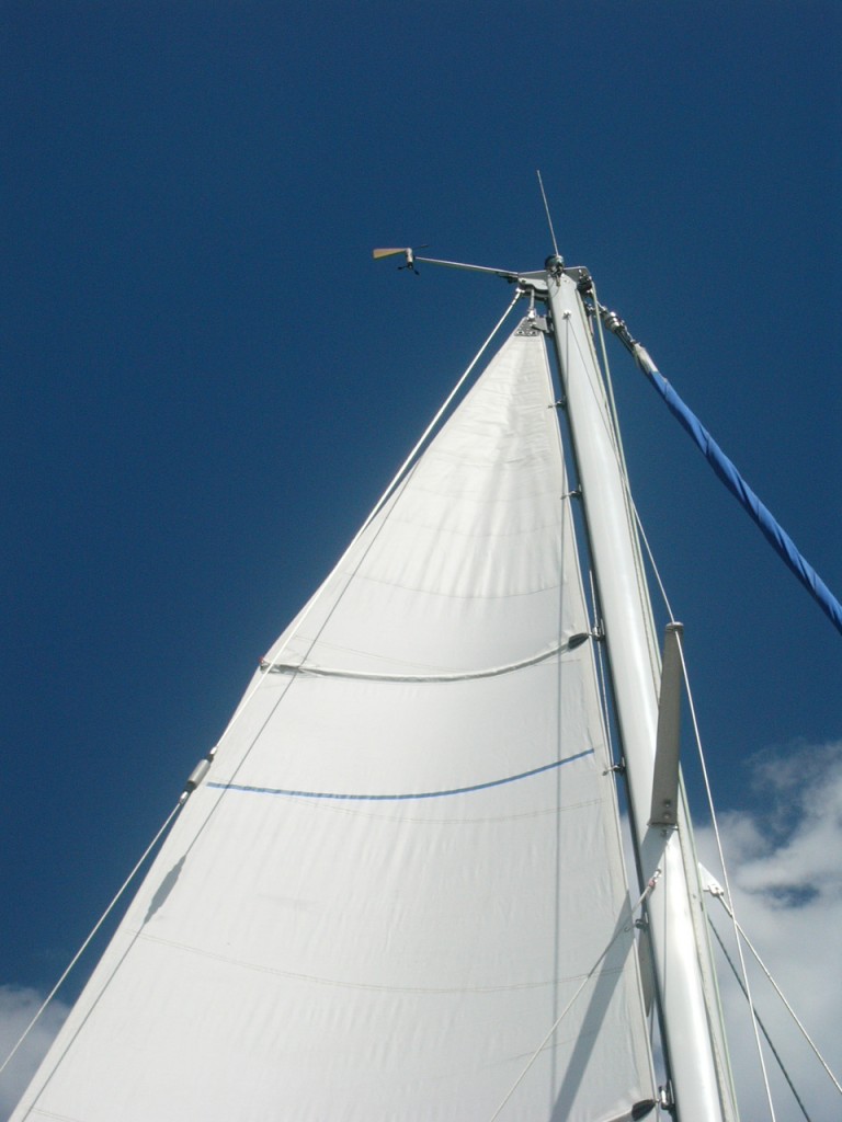
Full length Battens

Image


YES, NO, MAYBE, WHY?

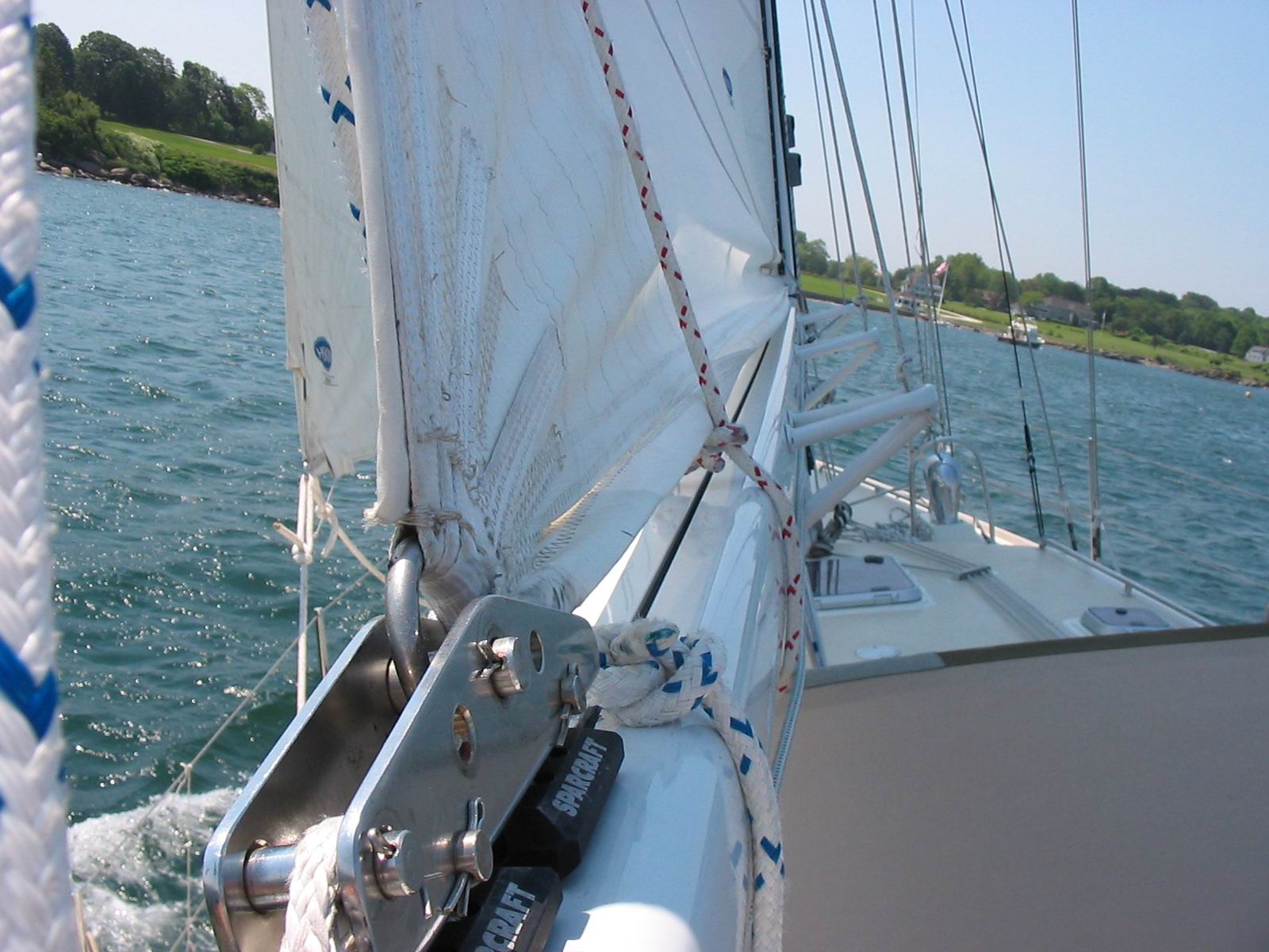
The subject of full length battens and whether or not you and your boat need them is one of the longer discussions sailmakers and their customers have. Like much else around the boat, there are plusses & minuses and maybes’ and what if’s. This series is intended to outline the various issues to be contemplated when you get the idea to have full length battens on your boat or new sail.

Briefly

What they can do:

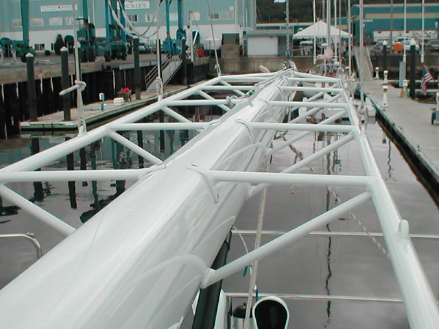
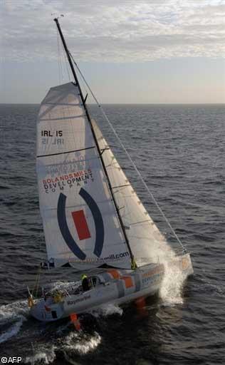
 A Class 40 with a so called Square Head mainsail

A Class 40 with a so called Square Head mainsail


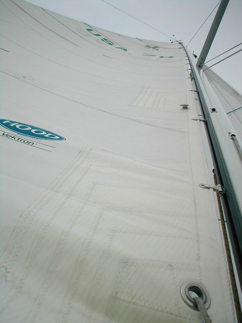
a)      Full length battens can support a more pronounced roach than a sail without full length battens.

b)      They can be retrofitted to revive the shape in an older sail

c)       They can make the mainsail “smoother” minimizing bumps, creases or hard spots at the forward end of short battens

d)      Maybe easier to flake and fold

Side rails to attach lazy jacks to.

Side rails to attach lazy jacks to.

e)      They can make capturing the sail as it is lowered less of a dance IF the boat has either a Dutchman OR a dedicated Lazy Jack’s system designed for the sail

f)       Reduce drag at the top of the spar, square head only

g)      They make the sound of the sail flapping less loud which has its own many benefits above the longevity of the sail fabric.


Issues to consider:

a)      Make the sail jump into its kennel all by itself–NOT

b)      Rating issues (if you do any kind of racing, an “oversized” mainsail will get a new handicap allowing for the perceived speed gain) with oversize roach, except when purely cruising or sailing open classes.

Kress LJ ears (1)

c)       Are they really faster as some have remarked?

d)      In the case of the large roach/square head sail the compression on the luff from the batten is considerable.

e)      Chafe esp. with aft swept spreaders. Also the batten pocket OR sail will chafe where the batten crosses the lee rigging when sailing down wind. It is perfectly possible to saw a hole through a sail overnight (I have inspected a sail so damaged) if this is not either addressed on the boat or in the construction phase of the sail.

f)       Whether to employ luff loading batten pockets or not. By this device the battens are inserted in the luff end of the sail with the leech end sewn shut thus making it really hard, as in you must really try to shake the batten out of the back of the sail. Much harder but not impossible.

OLYMPUS DIGITAL CAMERA

g)      The larger the boat (mainsail) the more likely the sail needs low friction track and cars.

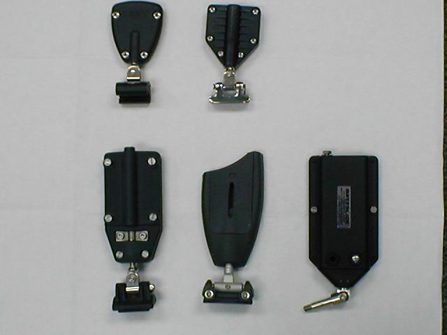
h)      Additional costs related to the detailing on the sail and the cost of the hardware.

A selection of available batten hardware

A selection of available batten hardware

i)        Value versus regular length battens

j)        Potential for damage when sailing-Like an all standing gybe where the sail lands up against the formerly windward runner usually with a great shock.

k)      The material from which the battens are made, there are mainly three flavors.

l)        Carrying spare (battens and parts) on voyages including the stowage on board, the shipping if necessary, the ease with which a long batten can be removed from the sail if the batten breaks

m)


Batten sliding systems

There are two categories:

  1. Those using a dedicated track and
  2. Ronstan track and car system

    Ronstan track and car system

  3. Those that do not have a dedicated track but rather the “cars” run in the mast’s original track/groove.

Within “A”: there are two sub-decisions, ball bearing cars and slider cars without bearings.

Within “B” there is one variation from the almost universal use of simply some kind of slippery plastic and that is a car that has bearings incorporated into the car itself. I am aware of only two products that fit this last description.


Components

There are three components to the fully battened system.

  1. The “cars” these may be simply a beefier version of the sail slug/slide the sailmakers might use anyway on a small boat’s mainsail. OR on bigger installations with ball bearing cars they are substantial pieces of engineering.
  2. The “batten box”, aka batten receptacle. The device into which the forward end of the batten is captured. This is in turn attached to the car by:
  3. Toggle”, aka universal. This can be as simple as webbing on a small sail or as complex as an unlimited multi axis universal ball joint on bigger hardware/boats.

There are of course all manner of small parts, screws bolts, nut, balls or slider inserts that are included in the various parts outlined above, but you get the idea


Do I want them or not?

Considering all the above the rational human would surely ask him/herself do I really want this headache versus what will I gain from having full length battens?


Read on.


Storm Jibs and Solent Stays

Regular readers will know of my enthusiasm for Solent stays as a great “Gear Change” for most conventional sailing boats. The Solent is particularly effective if the boat in question has a low aspect-ratio rig. That is the height divided by the J-this distance is roughly the forward side of mast at deck level forward to the head-stay fitting on the deck. So for instance a spar height (commonly referred to by riggers, mast makers & sailmakers as the “I”) of say 45 feet and a J of 15, is a three: one aspect ratio. A boat with a 47’ x 12’ rig is close to 4:1 aspect ratio.

And yes a tall skinny sail is just fine more or less—When sailing up wind close hauled—Only. For the average cruising boat high aspect-ratio sails are not so good. This has to do with both the strain on the head of the sail: the top of the sail tends to go very round in the head pretty quickly and more importantly, when the sheet is eased, the top of the sail twists off dramatically.  When adding foresails to the inventory, an owner would be well advised to consider the aspect ratio of the where the sail is to set.
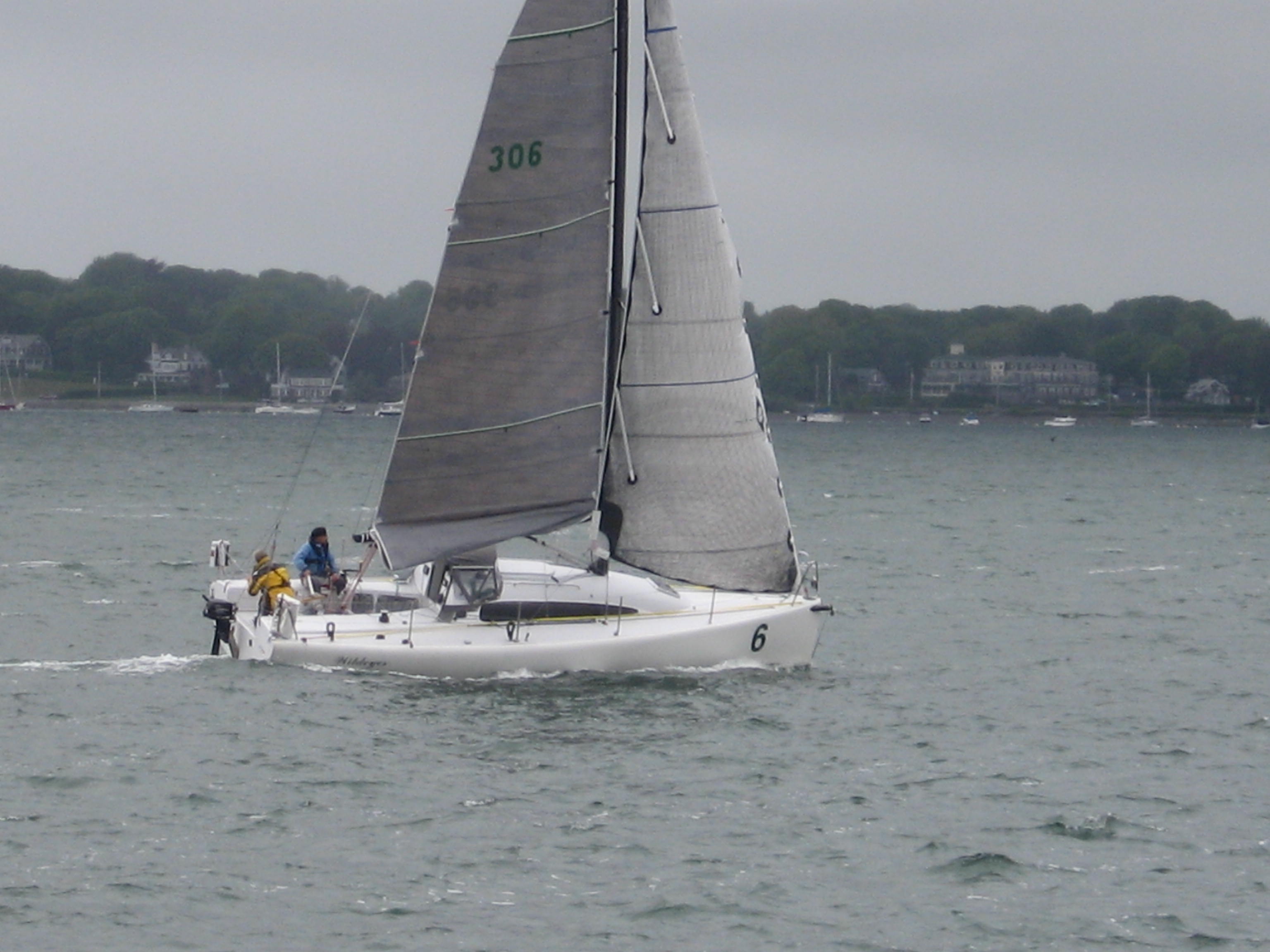
Quest 30 arriving in Newport. Headsail in use is the primary sail on the furler. You can see that the sail is relatively tall and skinny

With this in mind I have been working on just such a problem over the past month or so. A mate of mine is preparing his Quest 30 for the Bermuda 1-2—a solo race to Bermuda from Newport, RI then a DH race back from Bermuda to Newport. The Quest has an “I” of 41.0 feet and a “J” of 10.7 feet so again close to 4:1. Since the boat is to be sailing the ocean, simply relying on only one headsail on the furler  to sail across the most likely spectrum of winds between Newport and Bermuda in June is not a sound seaman like option. Especially with this type of furler which is merely a furler, not a reefing headstay.

The boat does not readily allow of a Solent set up, in the classic fashion–Roughly parallel to the headstay and a foot aft. Thus I had to design a system for setting a small sail that ended up being a Solent hybrid. A cross between a “cutter” stay and a Solent. In this  case the bottom of the stay lands very close to the stem head of the boat, like a Solent stay would. BUT the top of the stay lands at the second (top) spreader in the way a conventional Cutter stay might. There are a few reasons for this.
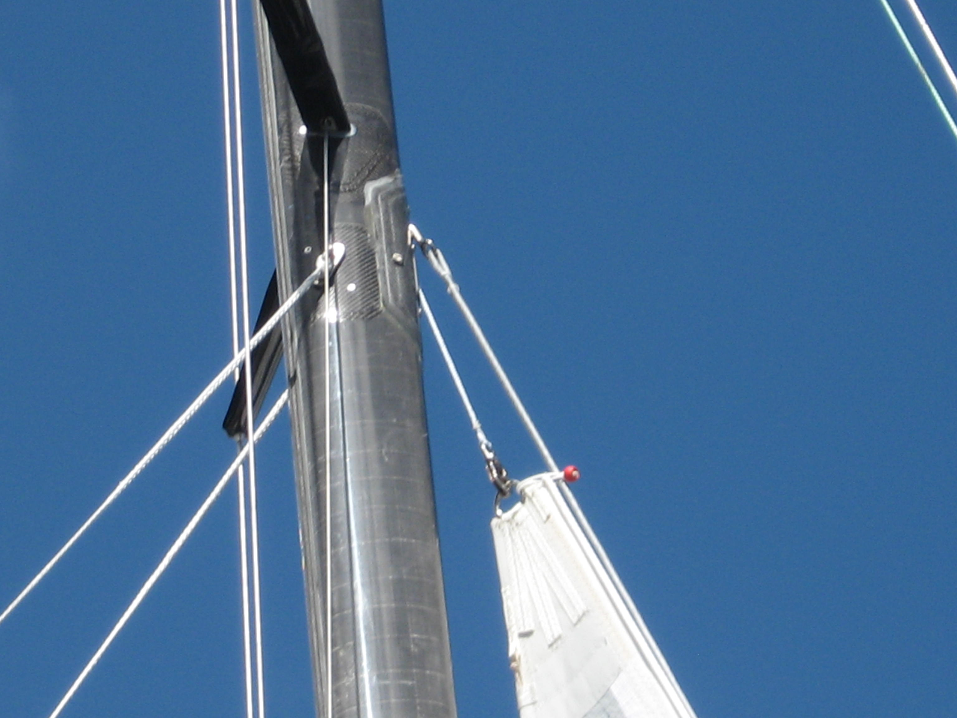
Primarily the fact that the spar had already the fittings necessary for a stay, runners, a sheave box and the halyard all at the top spreader-See image above.

So there were a lot of the basics for a stay on which a small sail could be set, with out re-designing the entire mast and deck layout. Overall  my goal was:

  • Design a system that could be deployed easily quickly and with the least amount of ruckus given that when it is going to be used, it will be blowing at least 25 kts.
  • Ideally the installation made use of the various equipment already installed and available on the boat-We did not have time or inclination to get into the boat building business.
  • Do it in a way that was cost effective, the more so since the entire staysail arrangement would only be rigged up on the spar and deck and perhaps not even deployed at all, every two years for the Bermuda 1-2. The rest of the time it will live in a bag in a locker somewhere.
  • Get it all designed, fabricated, installed and sea trialed as soon as could be done so any adjustments could be done in a timely given the start of the B-12 is 08 June.
There was also a fitting on the fore deck, very well secured to the aft edge of the anchor well, as is common however using this was not viable for several reasons I will get to.

I know this boat, intimately as it turns out:(I sailed this boat to Plymouth, UK in April 1996 so the then owner could sail it back in the OSTAR-But that is another story) So my first question was to look at the rest of the sail inventory to discover what headsails were to be carried in the race?

  1. The primary headsail is a 105% or so slightly high clewed jib set on a roller.
  2. The mainsail has three reefs. The head of the mainsail is below the top spreader when the third reef is set-Watch for this detail later-on in this post.
  3. There is a small sail called a storm jib, but having used this sail on the boat, I know it is a useless in practice. It is the wrong geometry completely.
  4. The boat has water ballast. This is in effect another gear/reef. As the wind comes on, rather than reefing, filling the water tanks is the equivalent of reducing sail.

The primary 105% furling headsail sets on a furler at the stem head, like normal, but not on a “normal” Harken type furler with a foil. It sets on a Facnor 4500 foil-less furler. As the images below show, the furler is very simple:
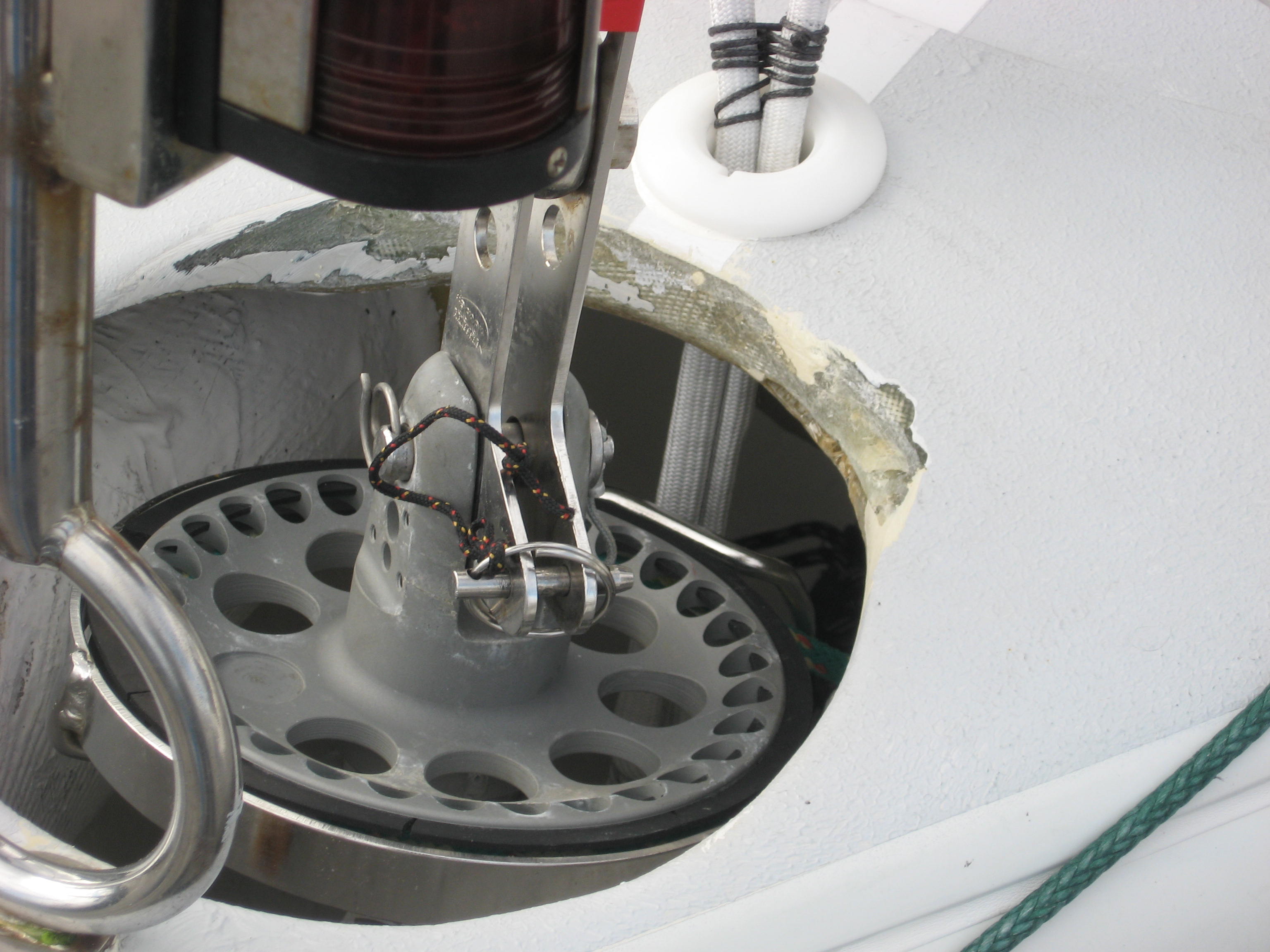
There is a stay made from 1×19 wire as is pretty normal. The tack of the sail attaches to the drum–You can see the horizontal pin with the key ring and light line holding it to the boat in the above picture. The drum is driven by an endless loop line (led aft) that rotates the drum and so the wire: the head swivel rotates freely. The sail is attached to the stay by the soft hanks made of Velcro.
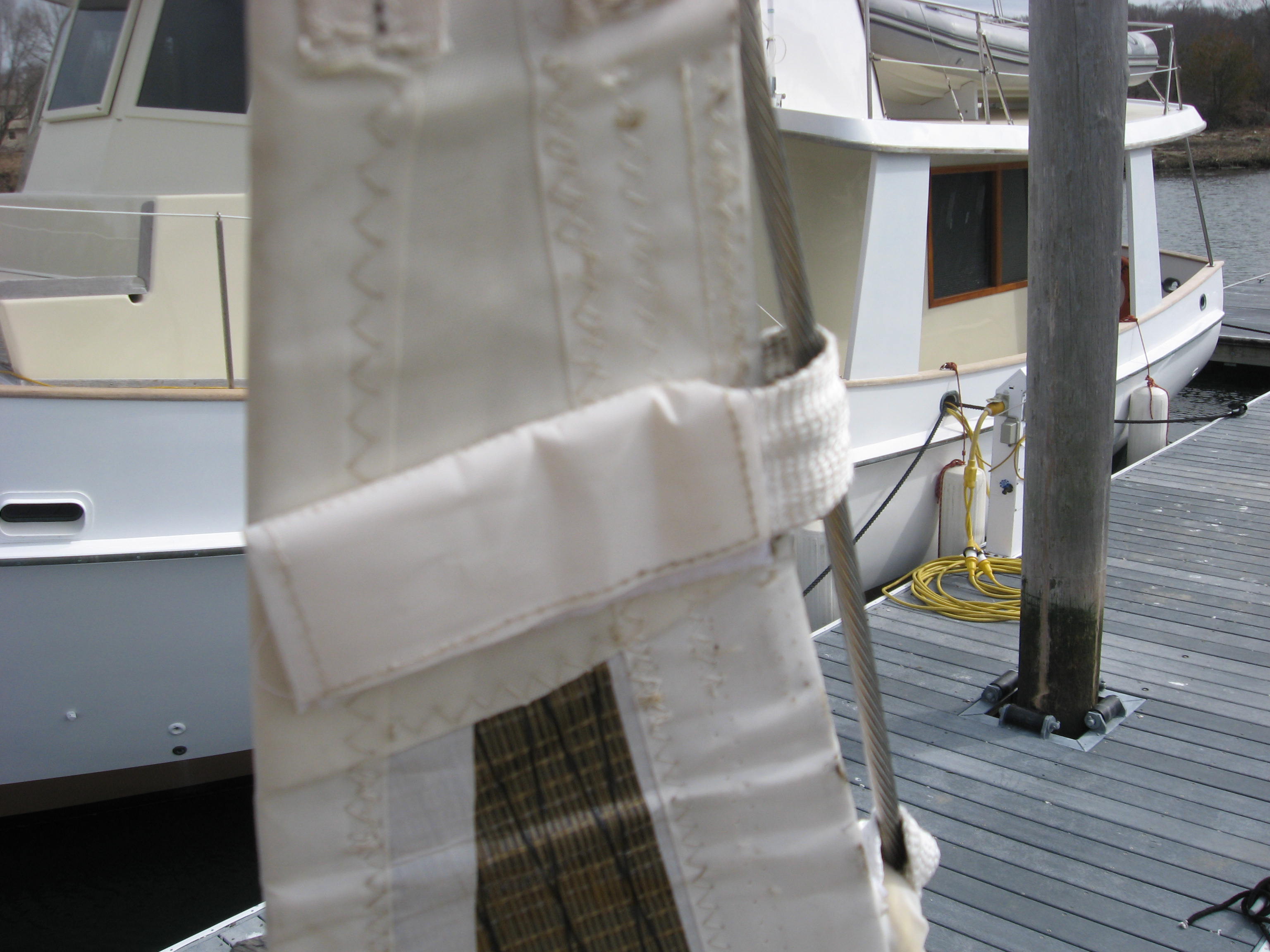
The sail is attached to the stay by “soft hanks” made of webbing and velcro

The idea here is to get the best of two worlds. A sail that can be furled, most of the time, BUT when it needs to be removed, it can be unrolled and lowered to the deck like a sail, with, well hanks-Just like the old days-So the sail is not going to blow all over the foredeck life lines and end up in the water.

The furler for the primary headsail is an foil-less furler. The Jib uses soft hanks connected over the wire stay. The grey cylinder is the top swivel

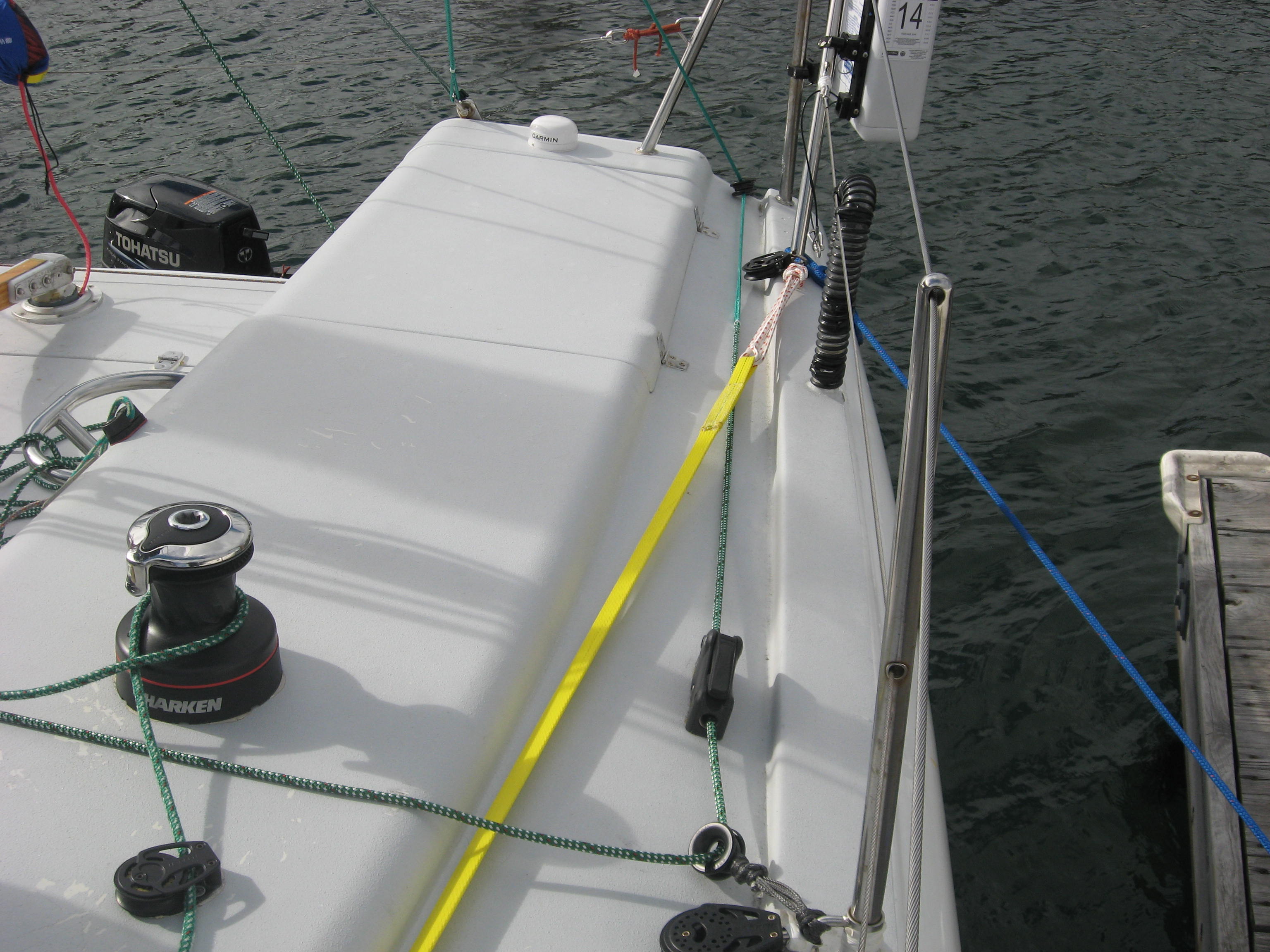
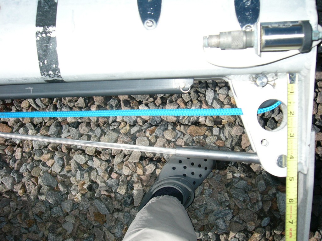
The white material aft of the drum attached to the tackle is a strop we fabricated to pass through the deck and connect to the headstay pin. To minimize chafe we installed a through-hull fitting into the deck for the strop to pass through. We attached a Wichard eye to the headstay pin and secured the strop to the eye with a soft shackle–The image seen below is a light line we used to line up the hole through the deck to the headstay pin.
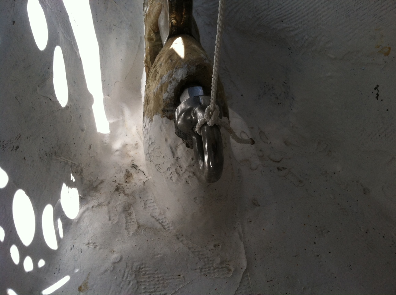
To anchor the bottom end of the stay, we threaded an eye to the aft end of the pin holding the headstay to the boat. The light line is a guide we used to line up the angle of the stay through the deck with the eye fitting so we could get the right location in the deck for the stay strop to pass thru.

BUT

In practice I cannot see unrolling this sail lowering it, (the material is pretty stiff and the sail has vertical battens-as seen in the top picture sailing into Newport Harbor), lowering it to the deck, removing the battens, flaking the sail, getting it in a bag, releasing the hanks, pulling the tack pin out, un-shackling the head of the sail from the swivel, without losing the shackle, getting the whole show below without losing anything over board, including  yourself, getting banged up yourself and then finally reversing the process with another small sail.

I cannot see that process talking less than an half an hour per sail even on a 30 footer.

So as a practical matter, the primary headsail would be furled up and a smaller sail set so the boat needed an inside stay.

A quick scan of the possibilities indicated that the best option would be to have a sail set from the top spreaders and landing just aft of the head-stay. Some of the issues to do with this that needed to be addressed included:

  • The main furler is installed below decks in the anchor well, so immediately aft of the forestay, there is nothing meaty enough to land a stay on.
  • Since the sail would go to the top spreaders, the rig would need running back-stays
  • If the small sail was to be set on the foredeck, at the aft end of the anchor locker, then the aspect ratio would be too tall and skinny-Not good geometry for a hard air sail, to be used in the ocean. The aspect ration of this triangle is over 3.5:1-too tall and skinny.
The pad eye in the foredeck was too far aft to either make for a good shaped sail nor would it be big enough, as can be seen in the picture below.
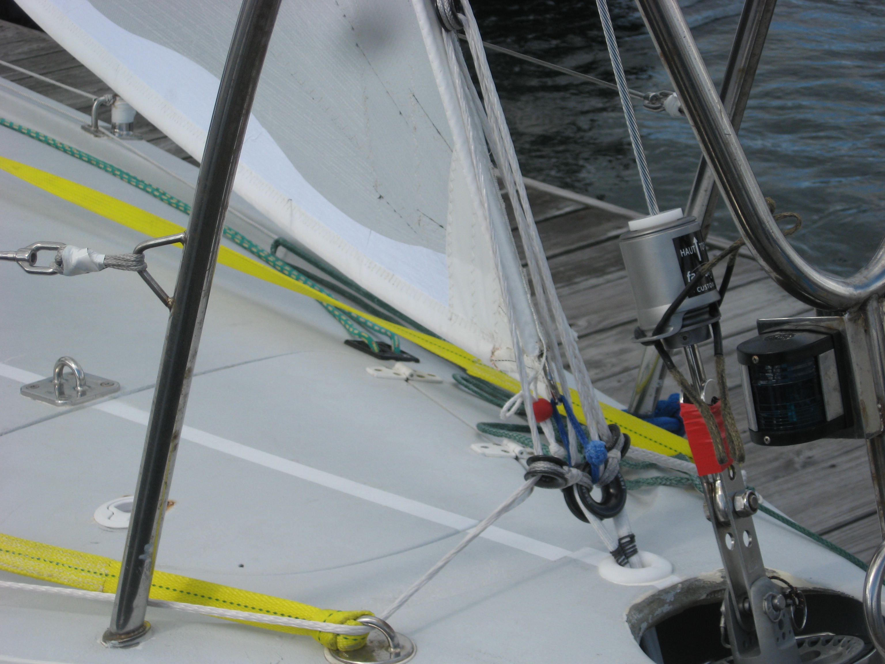
This image shows the location of the one pad eye aft of the stem, at the aft end of the anchor locker. (far left of picture) This was unsuitable because to install the stay tensioning tackle properly would have needed another couple of pad eyes AND the sail would be too small AND not very good geometry–Too high aspect. The results of what we did-Install a tackle and stay just abaft the stem-head, can be seen in this image.

“Normally” inside stays for most cruising boats today (although I am apparently single-handedly changing this), of any flavor use some kind of mechanical ratchet crank device or a Hy-Field lever. Both of these options are:

Heavy, difficult to handle, very difficult to tension after a while when everything as stretched in, and being heavy are awkward to man-handle around the foredeck when needed. They cannot be removed in a hurry as circumstances dictate.
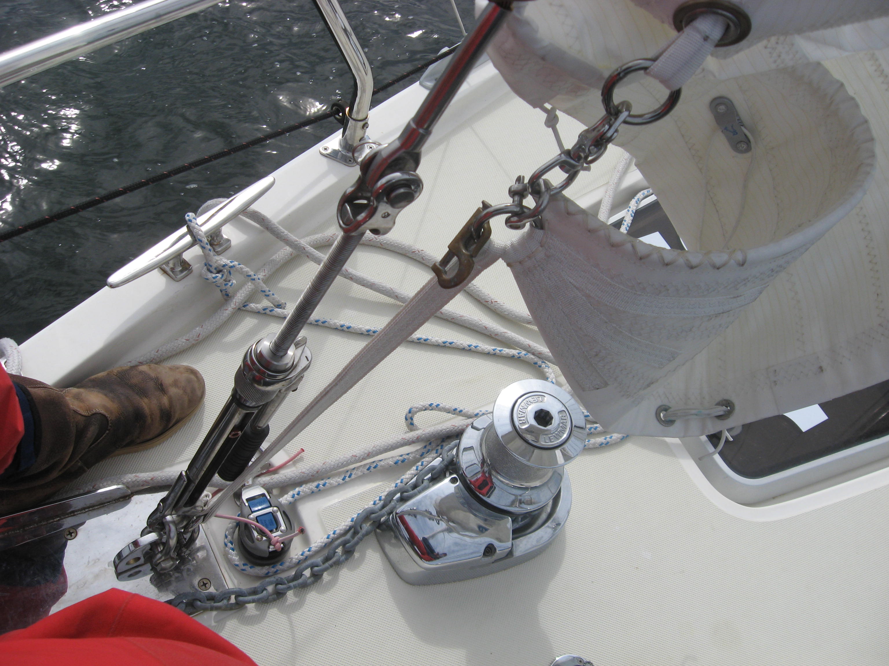
A Wichard hand crank adjuster on the Solent stay on a 44 footer, using a wire stay-This particular wire stay has been replaced by a textile stay that weights 5 pounds. Handling the crank, stay and a sail is way too much work and being heavy throws a lot of inertia around in the seaway that will be in evidence when this equipment is in use.

At the end of the day I designed a set up as follows:

Textile stay fabricated from a Spectra fiber product known to Hall Rigging, who made it for me, as Fiber wire.
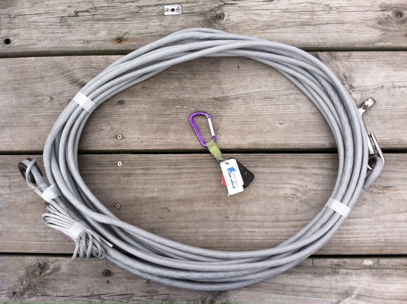
The Fiber Wire stay. The keys are to give idea of scale. The “T” fitting is visible on the right hand side

This stay attached to the spar using a T fitting, seen above

The bottom end of the stay was tensioned by a 4:1 tackle running through Antal thimbles.
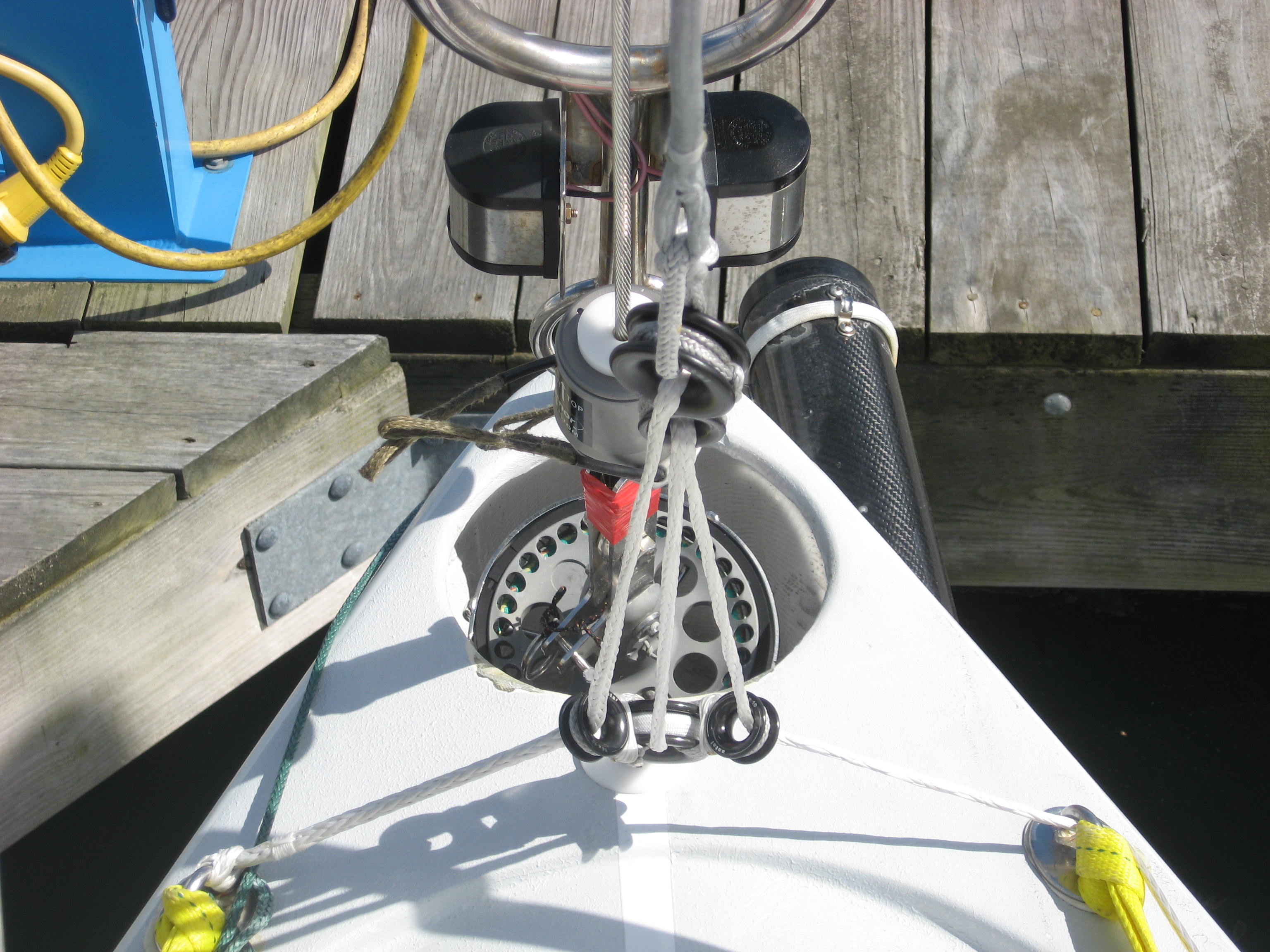
The stay is tensioned by a 4:1 tackle running through Antal thimbles

The tensioning line is dead ended on the port side and runs aft, through the pad eye on the starboard side to a clutch in front of another Antal thimble and from there the tail is long enough to go to any winch.
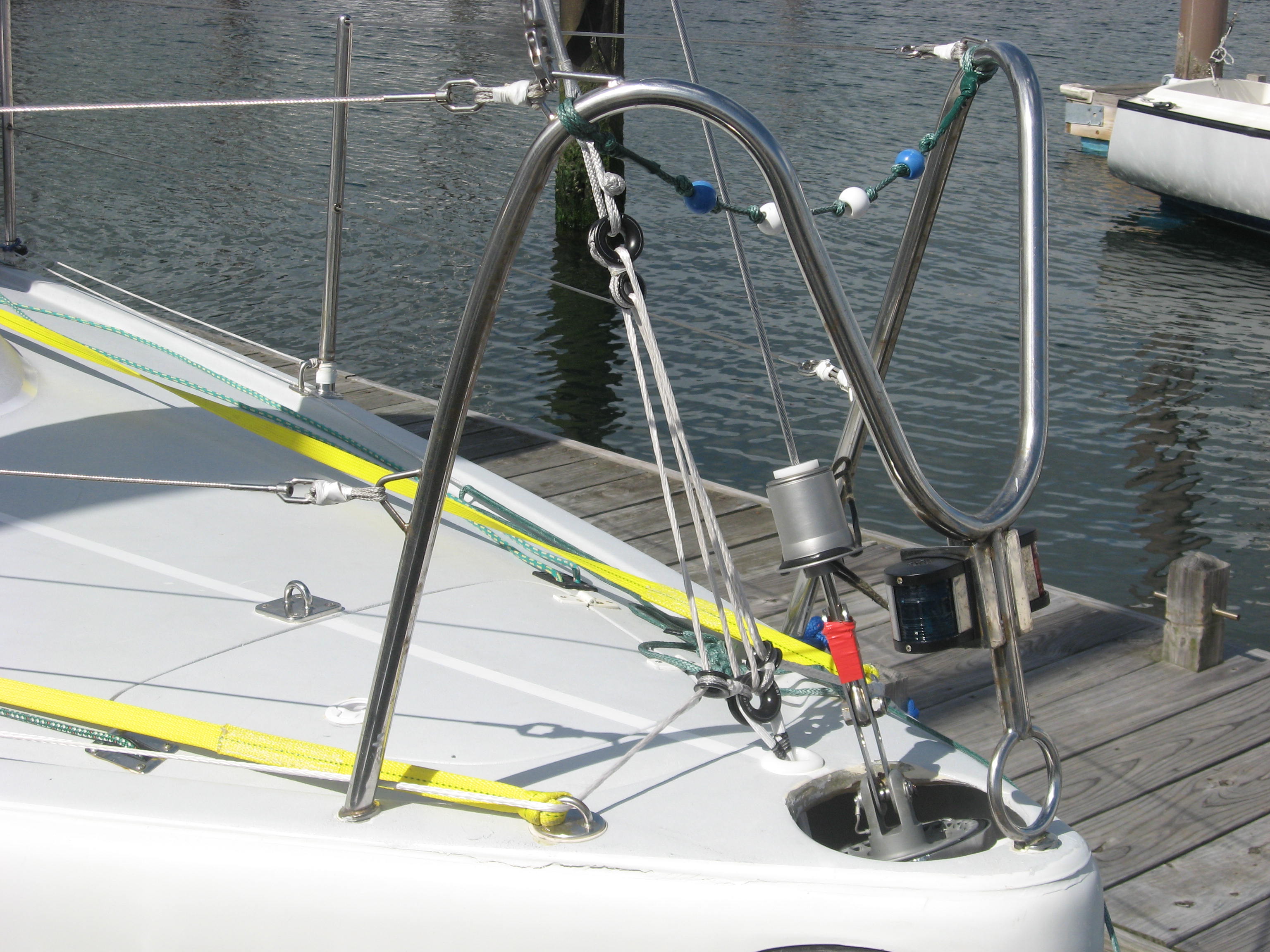
The stay is tensioned by a 4:1 tackle running through Antal thimbles

The stay is tensioned by a 4:1 tackle running through Antal thimbles. Since the line is not required to be adjusted all the time, the thimbles are perfect. They are light, strong, in-expensive in general and particularly when compared to a ball bearing block of equal strength, the latter by perhaps a factor of 10:1.
The knobby ball of cordage connecting the stay to the top thimble is a “soft shackle” an increasingly widely used device for attaching anything to something else, as one would with a stainless shackle

There are a pair of running backstays connected to the spar.
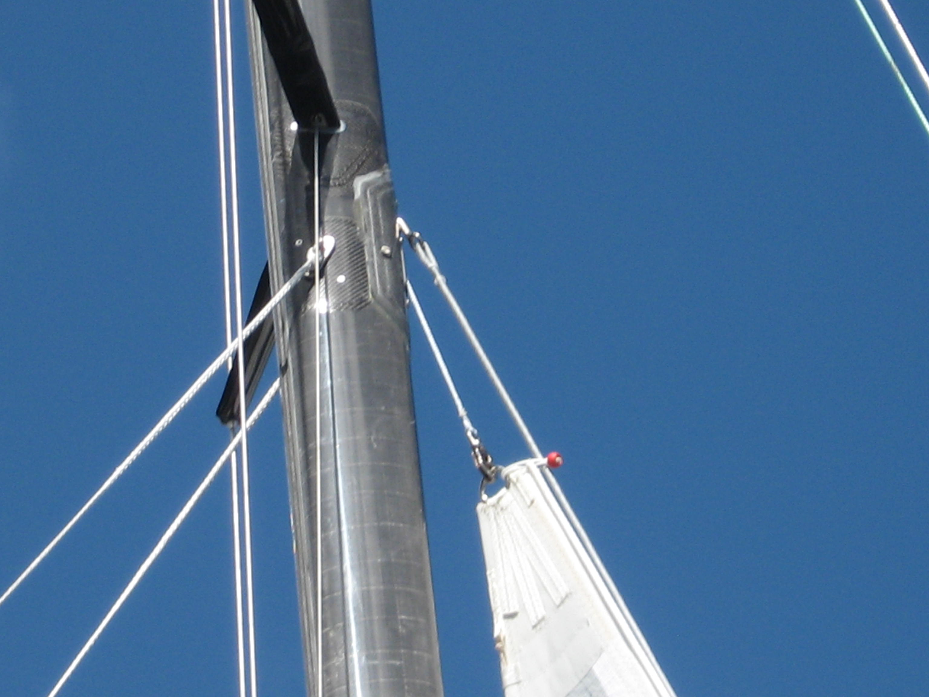
The running backstays are attached to the mast just below the upper spreaders and opposite the point where the inside stay connects to the spar. This is high enough that with the third ref in, the head of the sail is below the runners. The end of the boom is far enough forward that both runners can be set up and the boat can be gybed and tacked without handling the runners. An extra insurance policy on hard conditions.

These are tensioned by a 2:1 tackle led through Antal thimbles, to a clutch, thimble and again with enough tail to get to any winch.

I used himbles again on the flying part of the runners: They are light (does not hurt so much when it hits you in the head….)strong & inexpensive-A trifecta that is hard to beat.
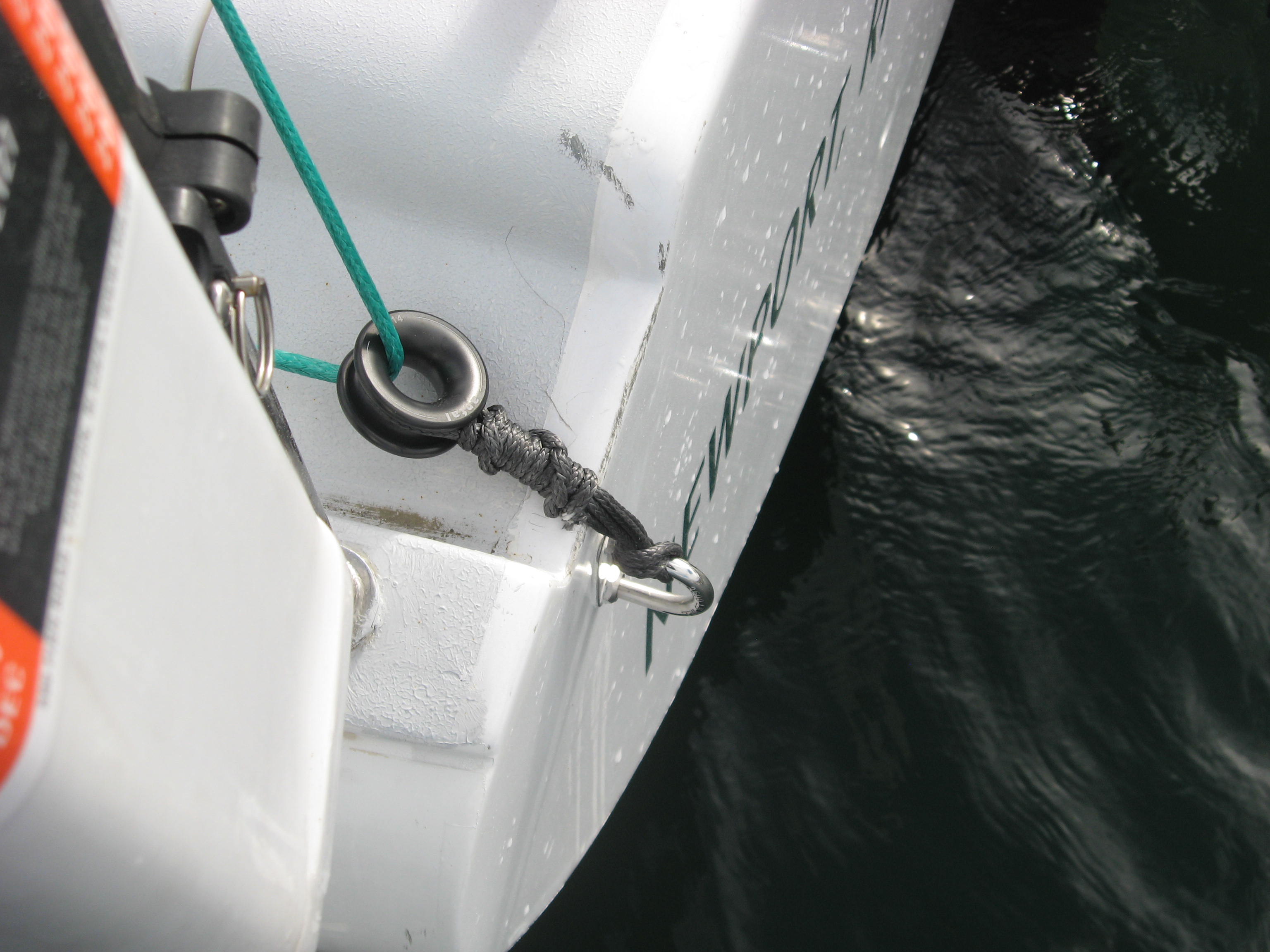
The running backstays are led through a thimble secured on the transom and forward through a clutch to another thimble permitting any winch to be used to tension them

The serendipitous aspect of the runners and where they land in the spar is that with the third reef in the mainsail the head of the sail is below where the runners attach to the mast AND the runners are sufficiently aft of the end of the boom, so BOTH runners can be set up when it is really howling and the boat can be tacked or gybed without attending to the runners. In this configuration the assumption is the inside stay will be deployed so the spar has another level of security to defend against damage.
The runner tails are dead ended on the same chain plate as the standing backstay, led up through the flying part of the runners, back to a thimble and forward through a clutch, thimble and so to any winch available.



Single handed sailing, old style

For those of us of a certain age, or with a passion and interest in long distance ocean-sailing, alone, the name Commander Bill King will trigger a ding in the dark recesses of the mental lazarette. Commander King was among the earliest sailors to attempt and subsequently, after the third attempt, successfully circumnavigate alone.

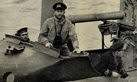
Picture of Commander King cut from an obituary in the British paper, The Guardian. The image was not attributed.

I remember reading his book “Capsize” as a teenager & being fascinated with the story. He had survived World War two as a submarine commander and apparently, according to various obituaries (he died in September at aged 102) was the only sub-captain to be in command of a sub on the first day of the war and still in command of (his third) sub at its conclusion.

His boat was designed by Angus Primrose, a Junk rigged Schooner, built in cold molded wood and unique, today, in having no life lines. He did have a jack line down the centerline of the boat though.

Galway Blazer was designed by Angus Primrose.  She was Junk Rigged-Image from the Junk Rig Association

I do remember reading, or perhaps surmising from his writings, that the mental toll taken as the Commander of a Submarine for 6 years was a major motivator in his interest in going to sea, on the surface, for a long time, alone. On his first attempt he was capsized in the vicinity Cape Town to which he was towed. He tried again in 1971 but adjourned to Fremantle due to illness. He subsequently tried again but ran into, or was run into by a large sea creature.  He finally left Freo. and made back to Plymouth UK on the third go.

That King is part of the very small pantheon of the pioneers of solo circumnavigation is without doubt but, he seems to have been a private man and did not pop up later  to become a public figure in sailing, or writing about, sailing.

Image of Commander Bill King

King in later life. Image from Yachting Monthly

My memory of King was re-ignited by an email I received last weekend from another circumnavigator, Scott Kuhner.  Scott and his wife, Kitty, have done I think two laps of the Blue Marble, the first in the early 1970’s, right about the time King was at sea of Cape Leeuwin, the SW corner of Australia. Scott is a recipient of my short-handed sailing emails and had sent me an email with a link to a video on King. I watched it and it confirmed my impressions from 40 plus years ago. In the video he makes reference to his reason for going off alone and the look in his face tells me he was reflecting back on what must have been an unbelievable 6 years.

If you think you are having, or have had, a bad-hair day, or even if you are not, watch this video.

Sails-Mainsail, measuring-E dimension

In a previous post I discussed the “P” dimension and the parameters surrounding the correct luff length; This post discusses the “E” dimension.
The “E” dimension is the second dimension (the first being “P”) that the boat’s designer uses in order to arrive at a mainsail size that he wants, in order for the boat to do what the person who commissioned the boat wants to do.

The “E” is for the purposes of 99% of the folks reading this essay, the distance from the aft face of the mast, aft along the boom, with the boom at right angles to the mast, to the inside (forward) edge of a contrasting colored band at the aft end of the boom”. For the other 1%, there are some minute variations on this definition, under the ORR rule.
Again, like the P dimension, the E is NOT the foot length of the actual sail and it is NOT the actual boom length. The reason the P and the E are not the actual sail edge length has to to do with two primary issues. One is the hardware (on the mast and boom)  by which the sail is physically attached to the spars and two, in most cases there is a deduction for stretch that sailmakers take or apply to a sail when designing it. This deduction is commonly different for each edge too.
As for the “P” let’s start with the “Black Bands.”

Some of these bands look like this.

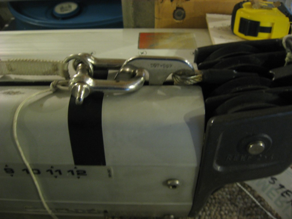
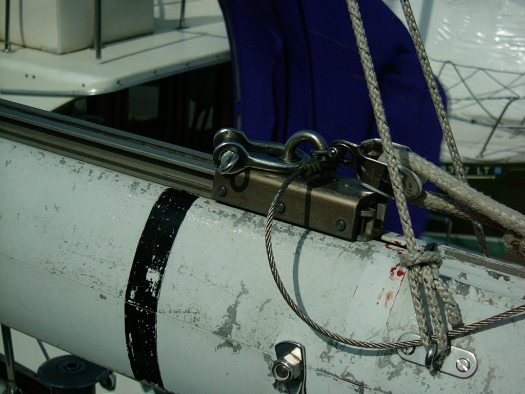
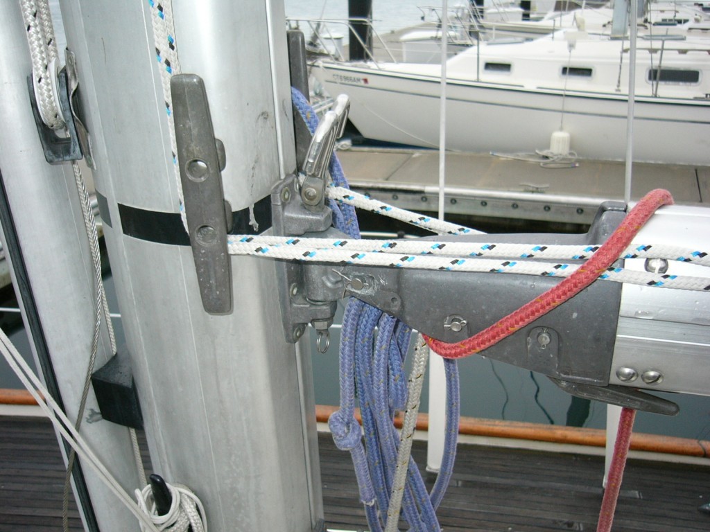
Black band on Caliber 40

Black band at the aft end of a Selden boom on a Caliber 40

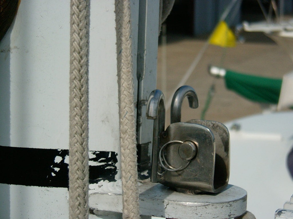
And here (below) although the paint or black tape is wearing off in this picture:

Cal 36 Black band at the clew

Black band at the clew end of the boom, Cal 36

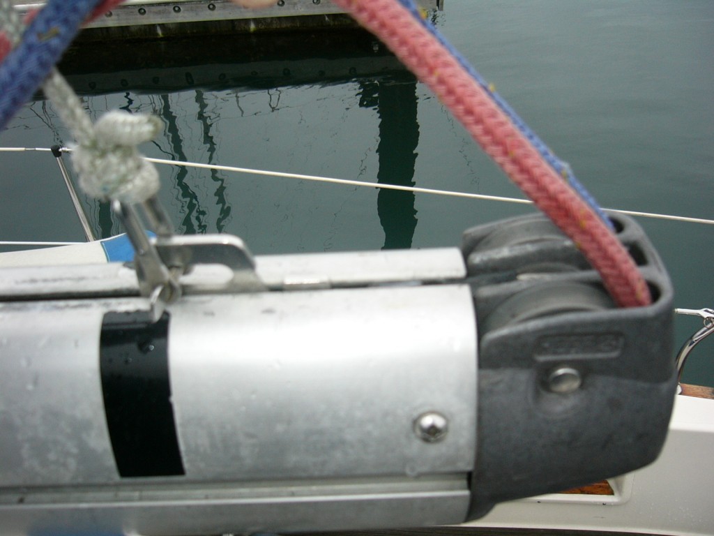
Notice too in the above picture  there is some space aft of the black band that “could” be used for sail outhaul. On the boom in the top picture the outhaul mechanism is fully extended, “two blocked”, as we might say, and the (bearing surface of the) shackle is just at the band.

And sometimes there is NO band. As here:

Sometimes there are no bands

Finding a boat without bands is pretty common, as on this Bristol 29-9

This next picture shows a detail than can be tricky:

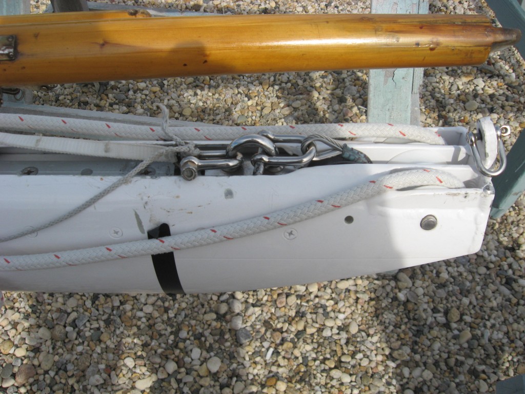
Black band at the clew on a 30 footer

Black band at the clew on a 30 footer

Observe (in the above picture) just aft of the stainless fitting with the halyard attached, in the boom tunnel, there are a couple of unidentifiable fittings? These are the swages connecting the outhaul wire to the outhaul fitting. There is just enough room aft of the black band to apply some more tension before the swage gets sucked into the sheaves, like is happening on the  boom shown below.

Sabre 38 clew band and outhaul  mechanism

Sabre 38 clew band and outhaul mechanism. On this boat the swage is pulled right into the sheave with the shackle at the band. See how the swage is bending?

So to recap:

The E is NOT the sail’s foot length

It is NOT how long the Boom is

It is the distance from the aft face of the mast, aft, to the forward edge of a colored band on the boom.

It is not uncommon for there to not be a colored band particularly on “cruising ” boats rigs.

I will discuss the particulars of four other sail making details in a future post.

Tack Set Back, Tack Set UP, Reef ring set back & Clew set up

Sails-Mainsail: The “P” dimension, defination and measurement of.

One of the things that gives most sailmakers gray hair is confirming the dimensions and details of fit for the sails they make. This selection of articles discusses the things sailmakers need to know and what the definitions are so the consumer can provide the correct information. There is nothing worse than getting down to the boat on that lovely Spring Saturday morning with the new sail only to find out the luff slides just don’t quite fit the track. Read on to find out how to help eliminate such frustrations.
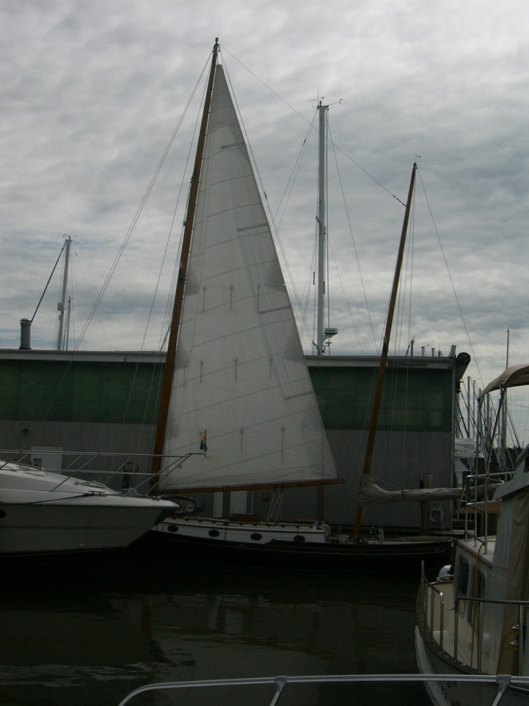
Virtually all boats have their “rig plan” defined by four dimensions. These are called the I, the J, the P, and the E. The I & J define the headsail and the P & E the mainsails. There are some other subcategories but let’s start with these four first and we will start with the mainsail and what the P & E dimensions are NOT.

  • The P is NOT the luff length of the actual sail.
  • And it is NOT the maximum available hoist on the mast.
  • The P dimension is NOT anything but this:

The distance up the mast (from the top of the boom) that the designer has calculated as the maximum luff length that a sailmaker might build a sail to (which, in conjunction with the other dimensions, I, J, E) will give the boat the sail area the designer wants it to have.

In plain English, “P” is in the first place a mathematical construct. In practice on most boats, especially those sold with “racer” in the name, the P is measured “from the UPPER edge of a contrasting color band at the gooseneck UP to the LOWER edge of a contrasting color band at the mast head.” This (is an approximate, but close) quote taken from most sail boat rating handicapping rules, like for instance PHRF, IRC and ORR. Any class or make of boat that desires to limit or control the mainsail area will make some definition similar to this. An example of what this (commonly called the black band for obvious reasons) looks like is this on a Hallberg Rassey 31 footer.

Selden Spars black band

The Black Band is located at the tack and P dimensions are taken from the top of the band to the underside of a similar band near the masthead.

Now the observant amongst you will say, “But the tack of the sail is a couple of inches above the upper edge of the black band!” Go to the top of the class- this is the nub of this article. That detail is called the tack set up and we will get to that detail. Another version of the black band is here.

Black band at tak Cal 36

Another view of the Black Band

And if the mast is black-Carbon or anodized-the band is white.

"Black Band" in White, on a Carbon spar

"Black Band" in White, on a Carbon spar

This “contrasting colored band” is at the gooseneck (so the lower) end of the P dimension.

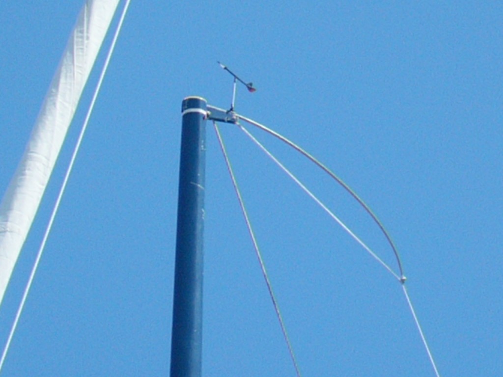
The top end is of course at the masthead, more or less. There are a few variables related to the positioning of the Upper Band of P. One fairly important one is the length of the backstay crane. This is the structure at the top of the mast to which the backstay is attached. The design and installation of the backstay crane varies over  time and boat design and intended use. In the case of older boats, and in particular boats with wooden masts, there is for practical purposes no backstay crane. So backstay crane’s come in all manner of configurations. The one of most interest to the sail makers is the length, I.E. the extent to which the crane and in particular, the attachment of the backstay to the crane is aft of the aft face of the mast.

The detail I am thinking about when measuring  this boat is making sure the sail does not foul the backstay when set to full hoist.

1. The height (length) of the luff of the mainsail is determined first by knowing the boat’s “P” dimension.

Mainsail crane clearance on 33 foot cuising boat.

The mainsail headboard needs to be able to clear the backstay at full hoist.

On many boats, especially “cruising” boats, like this Alajuela 33 pictured above there is no black band. Quite often the P is determined by consultation with any of the various compendiums of sail boat data sailmakers have at their disposal.The sailmakers must ensure that the mainsail headboard will not foul the backstay when the sail is at full hoist. The sail in the picture is actually at the “correct” height for the boat’s stated “P” dimensions (even though it looks “short”). This was confirmed, (reconciled really with data I had researched on the class of boat)  in advance of the new sail being made by measurement (by me) of the spar. If on the other hand the sail was built to full hoist, right up underneath the crane, it is most likely that the headboard would foul the backstay.

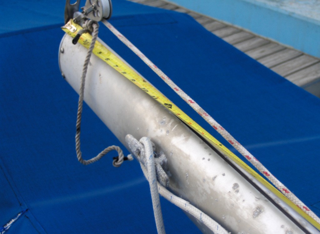
TIP: measure the spar fore and aft at your eyeball level standing on deck. Then eyeball the crane and visualize how long the crane is compared to the spar thickness. So if you reckon the mast is 8 inches long, fore and aft, and the crane is about 50% of the size of the spar, then a good estimate is the crane is 4″.

In this image, below, of an older wooden spar, there is no crane and no black band. Fortunately there is no backstay either. The line passing through the block is the topping lift.

Wooden mast with no backstay crane or backstay

Wooden mast with no backstay crane or backstay


2. The size (how long fore and aft) of the headboard and so how far aft the corner of the headboard may extend (including with all the luff hardware attached) aft of the aft face of the spar. The sail pictured below has a special headboard included with this luff hardware. On this boat the entire sail is about 1.5 inches further aft from the mast than it would be if the sail merely had “normal” slug slides.

Luff hardware has an impact on how far aft the headboard will extend

Luff hardware has an impact on how far aft the headboard will extend

3. The position of the backstay attachment to the crane.

On some racing oriented boats, like this Pearson Flyer, pictured below, the “P” is literally at the bottom of the main halyard sheave. Indicated in this instance with a white band on the blue spar. The crane is fairly long, for a 30 foot boat. The backstay is led through a, so called, “backstay flicker”, so that in light air the backstay can be eased to let the roach of the sail pass thru. Refer to more information on this in the Full Batten posts.

Race boats have the band very close to the top of the spar

Race boats have the band very close to the top of the spar

This absence of backstay crane is the main reason why there is often upwards of 18″ difference between the upper P measurement point and the “top of the mast” as is seen, below, on this wooden mast.

Headboard clears the backstay

The shorter the backstay crane is (or if absent completely) the lower down the sail must be

When you lower your old mainsail examine the anodized aluminum headboard for scarring on the after corner and if it is so marked almost for sure the sail has stretched to the point where it is fouling the backstay.
On some boats there is a backstay crane yet the band is still a ways down from the “max hoist” distance, as here.

 Black band position on Olsen 34

Close up of black band on Olsen 34 masthead. The black track is a Tides Marine Strong Track

You will observe that in this picture I am measuring the backstay crane so as to make sure what even headboard we select it will clear the backstay. How we figure that angle will be discussed in greater detail further on in this series, but basically we take a dimension from the gooseneck aft to where the backstay passes the end of the boom.

A common default measurement sailmakers use for determining the size of the headboard, stems from racing rules and that is 4% of the boats E dimension. So for a boat with a 12 foot E, then the default headboard would be 5.76, or basically a 6 inch headboard. Unless the boat is racing, and this is a detail of the transaction though the headboard would be shorter, for all the reasons discussed above.

So, to recap, the “P” is “the distance between the top of the lower band and the bottom of the upper band.”
It is not the luff length, the max hoist or anything else.
The “P” dimension and the “E” dimension, discussed in the next article, are the two pieces of information the sail maker will need to have to even begin to think about figuring out all the things he needs to consult with you on a new sail. Subsequent articles will discuss the detailing at the corners, tack set back, tack set up, reef set back and clew set up battens roach and a few other details pertinent to buying a new mainsail.